Master MTP Polarity Like a Pro
Filed under: Fiber
Comments: Comments Off on Master MTP Polarity Like a Pro

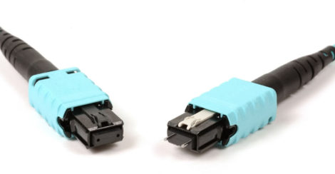
Multi-fiber push-on (MPO) connectors like the superior MTP with either 8 or 12 fibers are commonly used in the data center to either connect fiber panels in duplex applications or in end-to-end parallel optic applications like 40, 100, 200 and 400 Gbps that transmit and receive using 8 fibers (4 transmitting and 4 receiving at 25, 50 or 100 Gb/s). Regardless of the application, there is one thing that most data center designers and operators can agree on—MTP gender and polarity can be confusing.
When it comes to gender, each MTP is either pinned with pins or unpinned without pins to ensure proper alignment when mating two connectors. Since an MTP interface on active equipment is always pinned, what you plug into it must always be unpinned. That’s the easy part. Polarity on the other hand can be a bit more confusing.
What is Polarity?
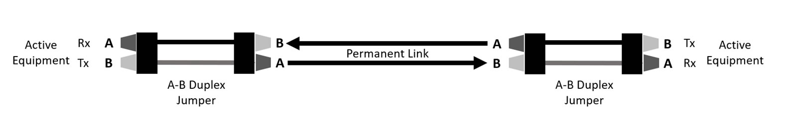
Proper polarity is required to ensure that the transmit signal at one end of a channel matches the corresponding receiver at the other end. The concept is fairly easy to grasp by reviewing a duplex application as shown in the graphic—A-B polarity for duplex jumpers maintains a straight-through connection so that B (transmit) at one end always corresponds with A (receive) at the other.
But polarity gets a bit tricky with MTPs where we now need to ensure that multiple fibers correspond correctly. All MPO connectors, including the MTP, features a key and an indicator (typically a white dot) to designate the location of the first fiber. The orientation of this key is essential to polarity. To add to the confusion, there are also three polarity methods available—Method A, Method B and Method C. Once you select a method, you need to stick with it throughout the channel.
Let’s take a closer look.
Method A
Method A uses Type A MTP trunk assemblies, which is a straight through connection where position 1 at one end of the assembly lines up with position 1 at the other end, and position 12 lines up with position 12, and so on. To accomplish this, one end of the assembly has the MTP in a key up position and the other has the MTP in a key down position.
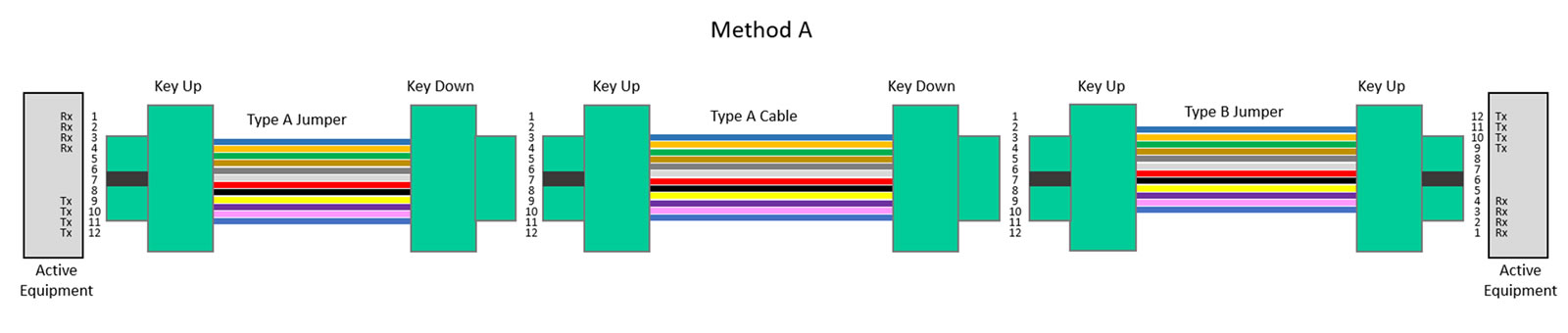
The crux of Method A is that to maintain a transmit-to-receive connection for the channel, one end requires a Type A jumper and the other requires a Type B jumper that uses a key up/key up scenario to enable the position 1 (receive) to eventually line up with position 12 (transmit) at the other end.
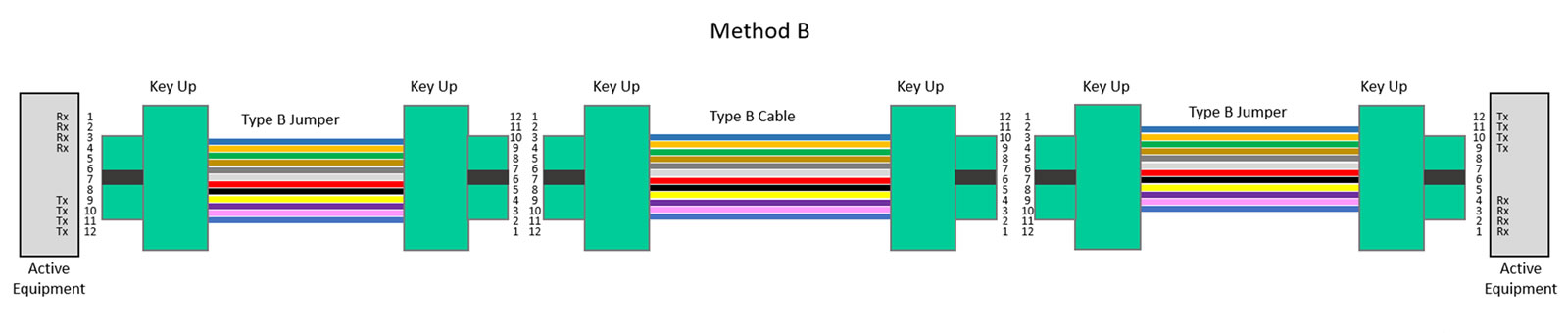
Method B
Method B uses Type B trunk cables (key up/key up) and Type B jumpers on both ends to make the corresponding transmit-receive connection throughout the channel. Because Method B uses the same type of components throughout, including both jumpers at either end, this is the most recommended method and the least likely to cause problems when used throughout the data center—if you don’t have any Type A components on hand, you don’t risk plugging them into your Method B channel.
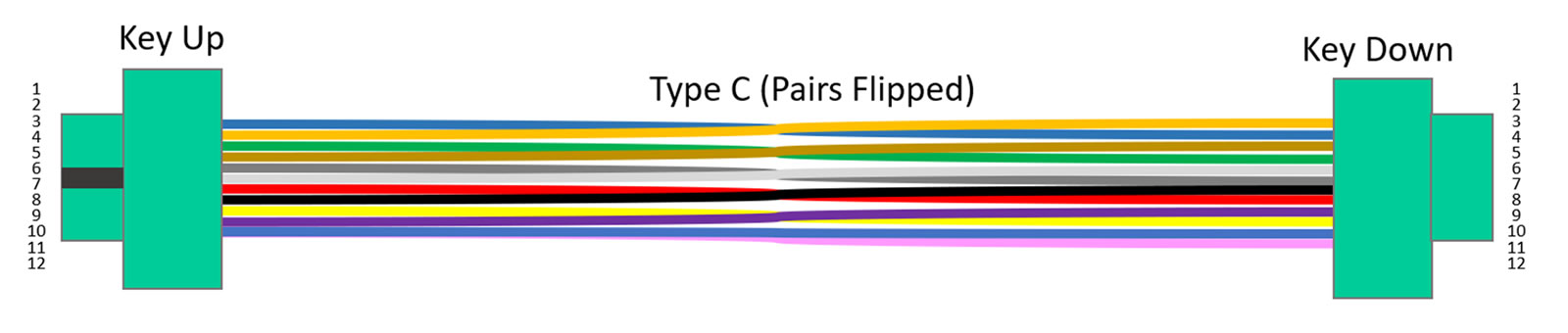
Method C
Method C is not recommended for parallel optic applications because Type C assemblies are cross-over assemblies that essentially flip the pairs within the cable so that position 1 arrives at position 2, position 2 arrives at position 1, and 3 to 4, 4 to 3, 5 to 6, 6 to 5, and so on. While this works well for duplex applications using Type A-B jumpers on both ends, it’s still not recommended since some day you may need to migrate from duplex to parallel.
When Things Go Wrong
Most issues surrounding polarity and gender happen on the jumper end of the channel in data centers that have mixed A and B polarity methods, where someone miscalculated or ordered the wrong polarity jumper for the channel. Gender issues are less common but can happen anytime the gender doesn’t allow you to connect to the active equipment (remember that active equipment is always pinned) or make the pinned-unpinned connection at adapters. And when this happens, you’re often stuck reordering and having to deal with additional expense, downtime or project delays.
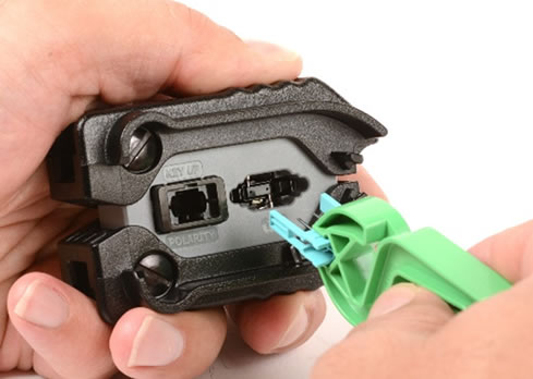
While it’s better to order the correct polarity and gender up front, and Siemon’s technical services team can help you figure that out, there is another solution—the MTP Pro connector. Now available on all Siemon’s Base 8 and Base 12 MTP trunk assemblies and hybrid MTP-to-LC assemblies, the MTP Pro offers the ability to change polarity and gender in the field using an innovative hand-held activation tool and pin exchangers.
So, if you mistakenly ordered only Type A jumpers for your Method A polarity when you need a Type B on one end, you can change the key up/key down Type A jumper to a key up/key up Type B and call it day. And if your jumper has a pinned connector on both ends and you need a unpinned to connect your equipment, you can change that too. It should however be noted that the MTP Pro does not work to change polarity on cross-over Type C assemblies or on singlemode due to the angled endface of the fibers, but it does work for changing gender.