ANSI/TIA-568.3-E Introduces New Polarity Methods

By Dave Valentukonis,

On September 29, 2022, ANSI released the latest revision of the ANSI/TIA-568.3-E, Optical Fiber Cabling and Components Standard.  A couple primary introductions of interest to most users will be the addition of two new connectivity (polarity) methods for array (MPO)-based duplex applications.  The revision also introduced revised guidance on pinning of connectors to better support future transition to end-to-end array systems.

Prior to the release of this revision of the Standard, connectivity methods for array-based duplex applications were limited to Methods A, B & C – each having its own strengths and weaknesses.  ANSI/TIA-568.3-E introduced two new “universal” methods: U1 and U2.  The advantage of these new methods is having the commonality components of Method B without the need for unique MPO*-to-LC modules on each end.  Customers can now use the same MPO-to-LC modules and duplex patch cords on either end of the channel in conjunction with a Type-B trunk – thus simplifying deployments.

Methods U1 and U2 both use Type-B array trunks and A-to-B duplex patch cords.  Where they differ is Method U1 uses Type-A (Key-Up to Key-Down) array adapters and Type-U1 fiber transitions which Method U2 uses Type-B (Key-Up to Key-Up) array adapters and Type-U2 fiber transitions as show below in Table 1 and Figure 1:

Connectivity MethodArray Trunk CableArray AdapterFiber TransitionDuplex Patch Cord
U1Type-BType-AType-U1A-to-B
U2Type-BType-U2

Table 1: New Duplex Connectivity Methods


Connectivity Method U1

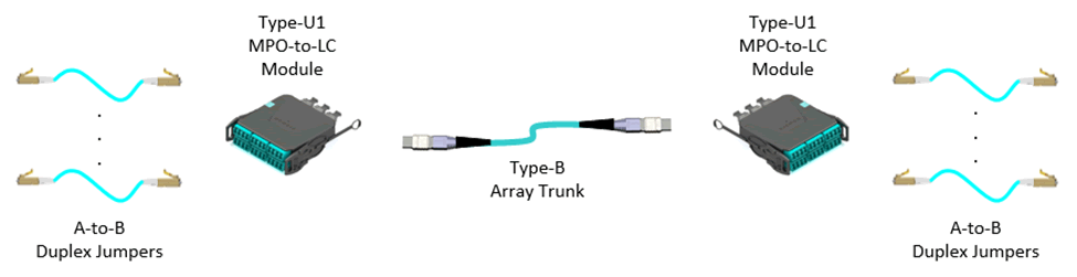
Figure 1: Connectivity Method U1


The key advantage of Method U1 vs Method U2 is that the use of Type-A adapters enables support of both multimode and singlemode applications as standard singlemode MPO connectors utilize opposing angled physical contact (APC) endfaces which are necessary to provide the more stringent return loss requirements of singlemode applications.

Additionally, Method U1 MPO-to-LC modules are ideal for use as a breakout or aggregation module for optical transceiver applications as shown below in Figure 2.  For more information, see Siemon’s Tech Brief 40 to 400G Optical Transceiver Breakout Links.

Breakout Application via Type-U1 MPO-to-LC Module

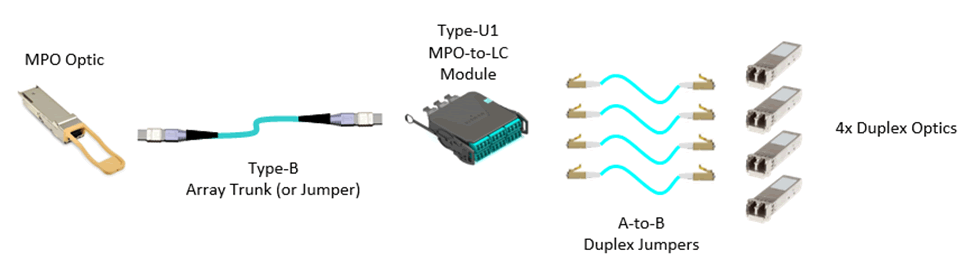
Figure 2: Breakout Application via Type-U1 MPO-to-LC Module


Additional MPO connector pinning guidance was also introduced in this new revision of the Standard to better enable future transition of an array-based duplex system to an end-to-end array system.  When mating MPO connectors – which use alignment pins – it is a requirement that one plug is pinned and the other plug is unpinned.  As MPO active equipment ports are pinned, they accept only unpinned plugs.

Therefore, an optimally designed array-based duplex system intended to support a future transition to an end-to-end array system should specify the following as illustrated in Figures 3 and 4:

  • Array trunk cables should be pinned on both ends
  • MPO connectors within the MPO-to-LC modules should be unpinned
  • Future array patch cords connecting MPO active equipment ports to the array cabling should be unpinned on both ends


Recommended Array-based Duplex System Pinning

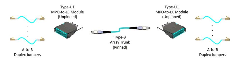
Figure 3: Recommended Array-based Duplex System Pinning


Recommended Array System Pinning

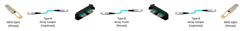
Figure 4: Recommended Array System Pinning


With the release of Siemon’s new LightVerse® fiber connectivity platform, Siemon offers Type-U1 MPO-to-LC modules with unpinned MPO connectors in both Base-8 and Base-12 as the standard offering and recommends the use pinned array trunks ensuring the simplest design and implementation of array-based duplex systems, breakout applications and future transition to end-to-end array systems.

* MPO is a generic reference – Siemon uses MTP connectors which are a premium MPO connector for all array connectivity products

Wi-Fi 7 is here – But what does that mean?

By Dave Valentukonis,

2022-08-wi-fi-7

Current estimates are that most (50-80%, depending on the country) of the world’s mobile data is carried on Wi-Fi devices. Driven by the exponential demand for throughput in support of a range of applications in our professional and personal lives (e.g. remote working and conferencing, Telehealth, IIoT/industry 4.0, IoT, AR/VR, wireless gaming, 4K and 8K video streaming to name a few), and as a result the specification of high performance network cabling supporting access layer switches and uplink connections has never been more critical to deliver the right capacity for next generation wireless access points.

With reports of the first Wi-Fi 7 routers already being released onto the market (well ahead of the projected standard release in 2024) it’s clear that for those organizations already planning future green-field and retrofit projects that Wi-Fi 7 is already something to be included in your design considerations.

What will be the technical advantages of Wi-Fi 7?

For the uninitiated, the IEEE is already actively working on the development of a new standard IEEE P802.11be™ “Enhancements for Extremely High Throughput (EHT) Wireless LAN” otherwise known as Wi-Fi 7. With an associated theoretical (46.1 Gb/s upstream and downstream combined) and “real world” (> 20 Gb/s upstream and downstream combined) maximum throughput, Wi-Fi 7 is intended to address your increasing application demands through a number of enhancements.

Most significant among these features is “multi-link operation” which allows for simultaneous transmission and reception enabling greater throughput and improved latency. Also, under consideration are expanded frequencies (including 6GHz), wider channels (including 320MHz) and better modulation (4096-QAM) – all while maintaining backwards compatibility with 11a/b/g/n/ac/ax Wi-Fi networks.

2022-08-wi-fi-7-figure

What does Wi-Fi 7 mean for the cabling infrastructure?

While IEEE P802.11be is not projected to be released until 2024, as we’re seeing, some of the key characteristics are sufficiently stable for some vendors to start releasing pre-standard Wi-Fi 7 devices, a trend that the market has also seen ahead of other Wi-Fi releases for 5, 6 and 6E. With preliminary throughput of > 18 Gb/s, these devices incorporate 2 x 10GBASE-T ports using link aggregation to support network uplinks.

In preparation for these higher speeds, multiple telecommunications standards, including ANSI/TIA-568.1-E, specifically recommend deploying two category 6A or higher cabling runs to each Wireless Access Point (WAP). Only class EA/ category 6A and higher rated network cabling provides guaranteed support of 10GBASE-T over all installation environments and channel topologies up to 100 meters.  Additionally, the use of shielded cables such as Siemon’s category 6A and category 7A ranges, in conjunction with our connectivity solutions which incorporate our innovative PowerGUARD® technology, provide the optimal approach when looking to support remote power delivery used to power these next generation Wi-Fi devices.

How can you best prepare for Wi-Fi 7?

The technology already exists to support your organization deliver exceptional Wi-Fi, and the right selection will lay an effective foundation for migrating to Wi-Fi 7 when the time is right for you. No matter where you are today in your Wi-Fi journey our team of technical experts are on-hand to support you in navigating your options. Don’t hesitate to get in touch.

Other links you may find interesting:

  Category: WiFi
  Comments: Comments Off on Wi-Fi 7 is here – But what does that mean?