Optical Network Tapping
Filed under: Fiber
Comments: Comments Off on Optical Network Tapping

Optical Network Tapping, also known as packet tapping or network monitoring, is a technique used to verify the performance and integrity of data streams as they flow between different devices on a network. This practice is often employed in data networks for various purposes, including network troubleshooting, security analysis, performance monitoring, and data collection. In this blog post, you will learn about the different types of network tapping, the most common optical split ratios, what a common network architecture looks like, and how to calculate the channel loss budget for a common network architecture.
What are the Different Types of Optical Network Tapping Available?
Tapping is the process of passively or actively monitoring network traffic by inserting a device called a network tap (traffic analysis point or test access point) into the network. There are two main types of network TAPs: Passive TAPs and Active TAPs
Passive TAPs are a hardware device, inserted into the network, designed to redirect a portion of the power on an optical circuit to an off-board network performance monitoring application. Passive taps are less expensive than active taps and do not introduce network lag, however, passive taps are also focused on network performance monitoring.
Active TAPs are a hardware device, inserted into the network, that direct 100% of the fiber to a third-party network analyzer; this network analyzer then replicates the traffic for further processing. The replication step provides a higher level of visibility but also introduces network lag as 100% of the traffic is replicated. While active taps are more expensive, a network manager has the ability to do more than just network monitoring, for instance, certain inspection applications allow for packet snooping and other similar services (utilizing SPAN – Switched Port Analyzer), thereby potentially damaging the integrity of the data.
SPAN is also available in two basic types. Local SPAN and Remote SPAN. Local SPAN mirrors traffic from one or more source ports on the same switch to one or more destination ports on the same switch. Remote SPAN (RSPAN) mirrors traffic from one or more source ports on one switch to one or more destination ports on another switch. However, they can impact network performance and the data they capture may not be forensically sound.
Whether using passive or active tapping, there are five common reasons to implement an optical network tapping infrastructure.
- Network Security: By monitoring network traffic, organizations can identify suspicious activities, potential security breaches, and unauthorized access attempts.
- Network Performance: Network administrators can use network tapping to analyze traffic patterns and identify bottlenecks or other performance issues in the network.
- Network Troubleshooting: Tapping can help diagnose network problems, such as connectivity issues, packet loss, or high latency, by providing insights into how data flows through the network.
- Compliance and Data Collection: In regulated industries, organizations might be required to monitor and record network traffic for compliance purposes. Network tapping can also be used to collect data for analysis and reporting.
- Intrusion Detection and Prevention Systems (IDPS): These systems monitor network traffic for signs of potential intrusion or malicious activity and can alert administrators or take automated actions to prevent attacks.
The focus of this tech brief is Passive TAP solutions. Passive hardware taps are placed in the data network optical fiber infrastructure between network equipment. They are typically connected between switch-to-switch links, for example, Spine switch to Leaf switch, supporting Ethernet protocol, or can also be used in Storage switch to Storage switch connections supporting Fibre Channel protocol.
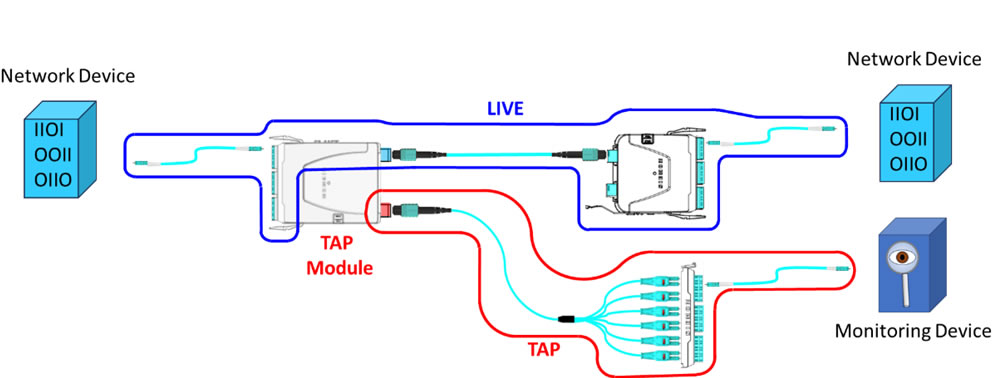
Figure 1: Sample switch-to-switch channel using a TAP module
Examining figure 1, this configuration is a basic structured cabling channel and is comprised of two MTP-to-LC modules connected by an MTP-to-MTP fiber trunk with LC-to-LC jumpers into the network device switch ports. The MTP- to-LC module on the left is the TAP module identified by the red MTP adapter in the rear of the module. From the rear, the MTP TAP port is connected to an LC adapter plate using an MTP-to-LC equipment cord which supports available TAP ports that plug into the monitoring device.
What are the Most Common TAP Split Ratios?
The optical signal in the TAP modules is commonly split into 50/50, 60/40, 70/30, 80/20 and 90/10 ratios. The first number is the portion of the signal to remain as live traffic, while the second number is the portion of the signal that is available for the TAP to utilize for the monitoring device. The 70/30 split ratio is mostly used for shorter distance links running at 1G to 10G. The 50/50 split ratio is the most common today as this better serves the higher speeds that today’s switch-to-switch links are operating at speeds of > 10G.
Passive TAPs work with both singlemode and multimode fiber regardless of the split ratios. As with standard fiber links, singlemode fiber has a longer reach than multimode fiber, especially in distances over 100 meters. The individual optical transceivers that are used in the switch-to-switch channels will have defined operating parameters by the manufacturer and provide specifications on the best fiber to use for the application.
How do TAPs factor into Loss Budget Calculations?
For the live network and the TAP monitor links to function properly, the loss budget for each path needs to be maintained. To determine this, the link insertion loss needs to be calculated. Table 1 below shows the different multimode TAP module component losses. If a performance issue arises, there is an option to look at other vendors optical transceivers. These other optics could provide less stringent loss budgets to better function for the channel that is to be tapped.
NOTE: The use of Siemon’s Ultra-Low Loss (ULL) MTP trunks, MTP-to-LC modules, and LC BladePatch® jumpers are required throughout the channel to meet the below performance specification and help minimize overall channel loss
| Component Loss (Max) | Multimode (OM4) | Singlemode |
|---|---|---|
| LC | 0.15 dB | 0.20 dB |
| MTP | 0.20 dB | 0.30 dB |
| Splitter 70/30 (Live/Tap) | 2.20/5.80 dB | 2.10/5.80 dB |
As an example, let’s calculate the link loss of the OM4 network shown in Figure 1, using a 70/30 split TAP module and Ultra-Low Loss (ULL) components. Note: The connections into the optical transceivers are not used in calculating loss budgets.
To start, in Figure 2 below, we have applied the connectivity losses to the model previously illustrated in Figure 1 :
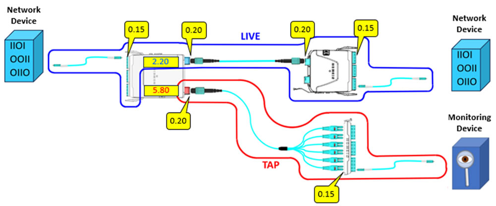
Figure 2: Sample channel using TAP module with component losses
For the live network link in blue, the calculation begins with adding the maximum loss for the live splitter segment in the TAP module of 2.20 dB as shown in Table 1. Next add the maximum loss for the MTP (0.20 dB) and LC (0.15 dB) connections on the TAP module which add up to 0.35 dB. Next, add the loss for the length of the fiber trunk in between the two MTP-to-LC modules. The maximum loss for this length of OM4 fiber is 0.30 dB at 100 meters. In most structured cabling implementations, the length of the MTP fiber trunk would be less than 100 meters, but for this example the maximum value will be used. Lastly, add the loss from the standard ULL MTP-to-LC module of 0.35 dB. The total maximum channel loss is 3.20 dB for the live channel as shown in Figure 3 .
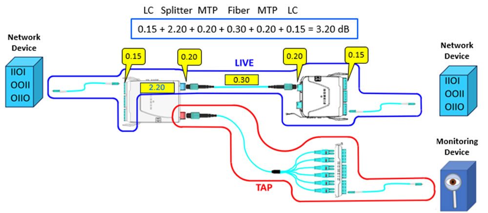
Figure 3: Multimode LIVE channel loss calculations
For the TAP monitor link shown in red, the calculation begins with adding the loss for the standard ULL MTP-to-LC module of 0.35 dB. Next, add the loss for the length of the fiber trunk in between the two MTP-to-LC modules. The maximum loss for this length is 0.30 dB at 100 meters. Then add the loss of the incoming MTP for the TAP module of 0.20 dB. Next add the tap splitter loss off 5.80 dB as shown in Table 1, and then add the loss of the outgoing MTP adapter of for the TAP module of 0.20 dB. For the purpose of this exercise, we will assume the MTP-to-LC breakout cable length is short, so loss is negligible. Lastly, add the loss from the LC adapter plate of 0.15 dB. The total maximum link loss is 7.00 dB for the tap portion of the OM4 network as shown in Figure 4 .
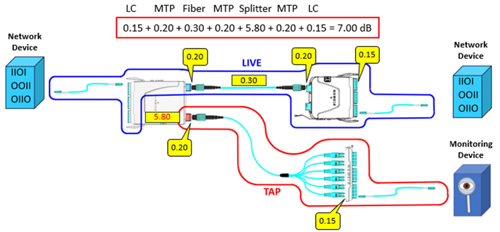
Figure 4: Multimode TAP channel loss calculations
The network architecture above is just one example of how to design an optical channel with passive TAP modules. Please contact your local Siemon representative for more information regarding other potential network architectures.
After reading this blog post on networking performance monitoring using passive TAP modules, you should know what a TAP module is, what the difference between active and passive network tapping, what the term optical split ratio means, how to calculate channel loss budgets and finally what a typical network architecture looks like. If you are looking to add network performance monitoring using Passive TAP modules, please reach out to Siemon today.