Why Use a Structured Cabling System?

By Dave Fredricks,

why-use-a-structured-cabling-system-feature

The global data center market is poised for substantial growth, projected to surge by over 6% year-over-year throughout this decade. This robust expansion is fueled by key technologies such as artificial intelligence (AI), internet streaming, and gaming, shaping the digital landscape in profound ways. Amidst this accelerating growth, data centers are evolving into sophisticated hubs, increasingly automated and equipped to handle diverse applications and a myriad of compute and storage devices, effectively managing the escalating workloads of the digital era.

In the dynamic realm of data centers, the importance of a well-designed structured cabling system cannot be overstated. Whether the device requires a copper or fiber connection, having a patch panel design makes it easier and more efficient for the myriad of changes and upgrades that can be expected in today’s fast-paced data center environments. The Telecommunications Industry Association (TIA) underscores this commitment through its TIA-942 standards, while the International Standards Organization (ISO) reinforces global compatibility with ISO/IEC 24764.

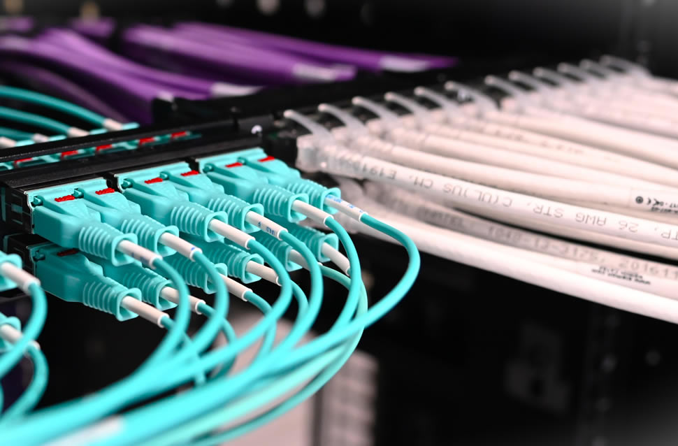
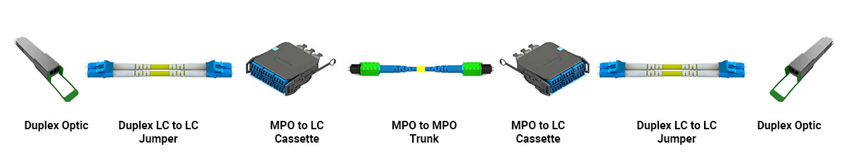
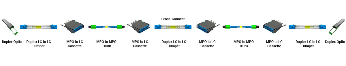
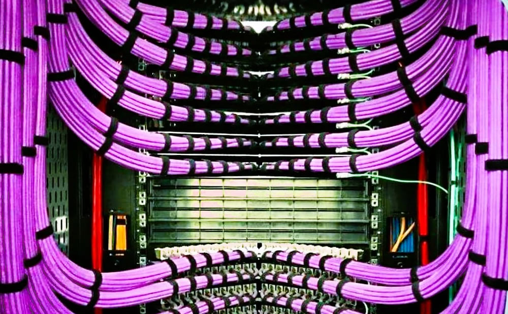
What is a structured cabling system? It’s a connectivity design that strategically places patch panels or enclosures throughout the data center space so connecting devices into the network can be accomplished with short patch cords or jumpers. The connectivity between the patch panels and enclosures is considered “structured” and remains in place for years while the end connections of patch cords and jumpers into the devices can be plugged into and out of the cabling system. For a visual representation, see Figure 1, showcasing a common fiber structured cabling channel supporting duplex LC fiber connections. It’s important to note that the optical transceivers that the compute and storage devices require dictate what type of fiber and connector is to be used. These compute and storage devices can often operate on different fiber types and connector types. The choice of fiber and connector type is best determined by the application in relation to the speed and distance of the connection. With proper planning, the structured cabling infrastructure can be specified to support multiple generations of data center applications eliminating the need to re-cable for each upgrade.

Figure 1

why-use-a-structured-cabling-system-1

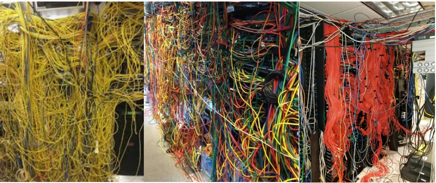
The opposite of a structured cabling system is point-to-point cabling. This connectivity method is less expensive, requires little planning and is easy to execute at the beginning. The downside to point-to-point cabling is when new devices need to be added, moved or removed from the network. Upgrades often require new cables and existing cables are often left in place creating unnecessary pathway congestion. When installing a new point-to-point cable, the technician often uses a cable that is longer than is needed to make sure there is sufficient length to connect the devices on each end. As time goes on these “extra length” cables become difficult to manage and they block air pathways in cabinets and racks that are used to cool the data center equipment. This in turn increases the amount of energy needed to cool the compute and storage devices. As illustrated in the photos below, the once neatly installed fiber cabling begins to resemble a tangled web, challenging to navigate and manage. The inefficiency of point-to-point cabling, once masked by its initial ease of execution, now takes center stage, emphasizing the importance of a well-thought-out structured cabling system.

Figure 2

why-use-a-structured-cabling-system-2

A structured cabling system offers many advantages over point-to-point in the data center space. Below are seven main reasons:

  1. Ease of Management: Structured cabling provides a systematic and organized approach to managing cables within the data center. It allows for easy identification, tracing, and management of cables, which simplifies maintenance and troubleshooting tasks. Cable trunks or bundles reduce pathway conveyance and conduit space allowing for more cabling growth.
  2. Scalability: Structured cabling systems are designed to accommodate future growth and changes in technology. They can easily adapt to accommodate additional equipment, upgrades, and expansions within the data center environment without requiring significant reconfiguration or downtime. Structured cabling allows the use of multiple generations of compute and storage equipment to work together seamlessly even with different connector types.
  3. Reliability and Performance: A well-designed structured cabling system minimizes signal interference, crosstalk, and other issues that can degrade network performance. This ensures reliable and consistent data transmission speeds throughout the data center, which is crucial for maintaining optimal operational efficiency. A structured cable system installed by a Siemon Certified Installer has a 25-year warranty.
  4. Flexibility: Structured cabling systems offer flexibility in terms of supporting various types of network equipment and technologies. They can accommodate different networking standards, protocols, applications, and optical transceivers to allow data center operators to easily integrate new devices and technologies as needed. Any relocation of equipment simply requires changes to patch cords instead of having to re-install new cabling.
  5. Reduced Downtime: By minimizing cable clutter, simplifying cable management, and providing consistent administration, structured cabling helps reduce the risk of accidental cable disconnections and other human errors that can lead to network downtime. This helps improve the overall reliability and availability of services within the data center.
  6. Cost-Effectiveness: While the initial investment in structured cabling may be higher compared to traditional cabling methods, it offers long-term cost savings by reducing maintenance costs, minimizing downtime, and providing a scalable infrastructure that can adapt to changing business needs over time.
  7. Standards Compliance: As mentioned earlier, TIA-942 and ISO/IEC 24764 industry Standards detail best practices to ensure compatibility with a wide range of networking equipment and technologies. This helps simplify interoperability and integration efforts within the data center environment.

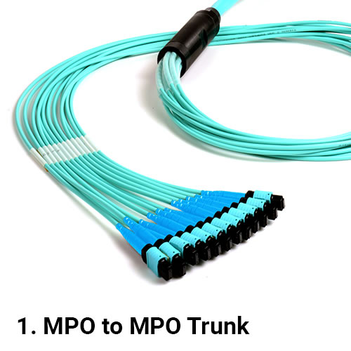
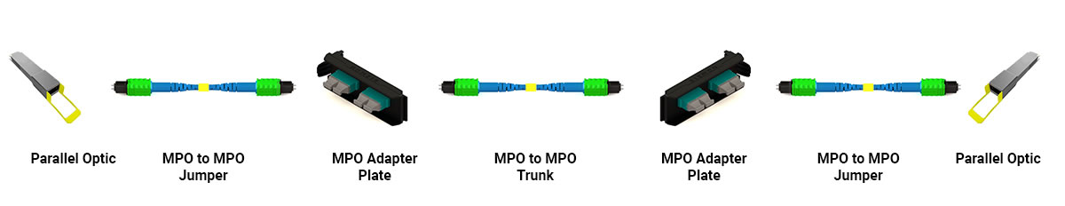
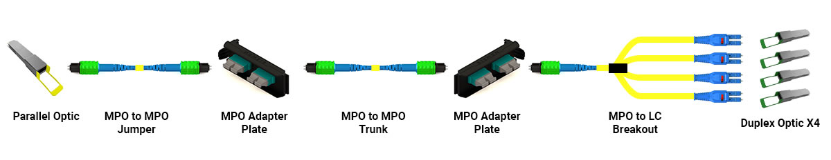
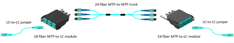
As AI computing and storage devices are installed into the data center, more fiber cabling is needed to support the higher speeds required for the graphics processing units (GPU) to function properly. A basic AI compute architecture has 128 nodes or servers with 16 spine and 32 leaf switches. The number of compute fiber strands between these devices is 8192! This number of fibers does not include the Storage, In-Band and Out-of-Band management connectivity needed for the architecture. Having a structured cabling system to support connectivity between the network racks and the servers and switches helps manage all these cables. Figure 3 provides a glimpse into the anatomy of a common AI channel using multimode fiber with angled (APC) MTP connectors that hold 8 fibers each. The MTP-to-MTP trunks can scale up in fiber counts to best match the application.

Figure 3

why-use-a-structured-cabling-system-3

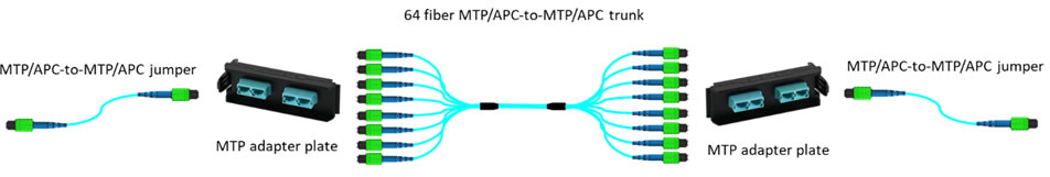
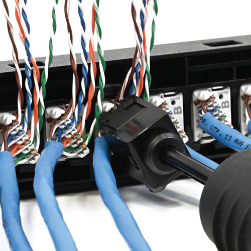
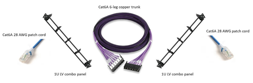
Structured copper cabling systems are also used in the data center. Copper trunks speed up cabling deployments by eliminating the time needed for connector terminations. Figure 4 illustrates a typical structured copper trunk application. It becomes evident that the strategic implementation of these trunks can significantly contribute to the overall efficiency and reliability of a data center’s cabling system.

Figure 4

why-use-a-structured-cabling-system-4

In summary, in the world of data centers, machine learning, and AI, it is not just about computing power and sophisticated algorithms; it’s also about the silent workhorses behind the scenes – the well-structured fiber or copper cabling systems that enable these technological marvels to function seamlessly. So, the next time you marvel at the capabilities of data centers and AI, take a moment to appreciate the intricate dance of connectivity making it all possible.

Want to learn about Siemon AI Solutions? Visit our Generative AI webpage at www.siemon.com/ai.

Optical Network Tapping

By Dave Fredricks,

Optical Network Tapping Feature

Optical Network Tapping, also known as packet tapping or network monitoring, is a technique used to verify the performance and integrity of data streams as they flow between different devices on a network. This practice is often employed in data networks for various purposes, including network troubleshooting, security analysis, performance monitoring, and data collection. In this blog post, you will learn about the different types of network tapping, the most common optical split ratios, what a common network architecture looks like, and how to calculate the channel loss budget for a common network architecture.

What are the Different Types of Optical Network Tapping Available?

Tapping is the process of passively or actively monitoring network traffic by inserting a device called a network tap (traffic analysis point or test access point) into the network. There are two main types of network TAPs: Passive TAPs and Active TAPs

Passive TAPs are a hardware device, inserted into the network, designed to redirect a portion of the power on an optical circuit to an off-board network performance monitoring application. Passive taps are less expensive than active taps and do not introduce network lag, however, passive taps are also focused on network performance monitoring.

Active TAPs are a hardware device, inserted into the network, that direct 100% of the fiber to a third-party network analyzer; this network analyzer then replicates the traffic for further processing. The replication step provides a higher level of visibility but also introduces network lag as 100% of the traffic is replicated. While active taps are more expensive, a network manager has the ability to do more than just network monitoring, for instance, certain inspection applications allow for packet snooping and other similar services (utilizing SPAN – Switched Port Analyzer), thereby potentially damaging the integrity of the data.

SPAN is also available in two basic types. Local SPAN and Remote SPAN. Local SPAN mirrors traffic from one or more source ports on the same switch to one or more destination ports on the same switch. Remote SPAN (RSPAN) mirrors traffic from one or more source ports on one switch to one or more destination ports on another switch. However, they can impact network performance and the data they capture may not be forensically sound.

Whether using passive or active tapping, there are five common reasons to implement an optical network tapping infrastructure.

  1. Network Security: By monitoring network traffic, organizations can identify suspicious activities, potential security breaches, and unauthorized access attempts.
  2. Network Performance: Network administrators can use network tapping to analyze traffic patterns and identify bottlenecks or other performance issues in the network.
  3. Network Troubleshooting: Tapping can help diagnose network problems, such as connectivity issues, packet loss, or high latency, by providing insights into how data flows through the network.
  4. Compliance and Data Collection: In regulated industries, organizations might be required to monitor and record network traffic for compliance purposes. Network tapping can also be used to collect data for analysis and reporting.
  5. Intrusion Detection and Prevention Systems (IDPS): These systems monitor network traffic for signs of potential intrusion or malicious activity and can alert administrators or take automated actions to prevent attacks.

The focus of this tech brief is Passive TAP solutions. Passive hardware taps are placed in the data network optical fiber infrastructure between network equipment. They are typically connected between switch-to-switch links, for example, Spine switch to Leaf switch, supporting Ethernet protocol, or can also be used in Storage switch to Storage switch connections supporting Fibre Channel protocol.

Optical Network Tapping figure-1

Figure 1: Sample switch-to-switch channel using a TAP module

Examining figure 1, this configuration is a basic structured cabling channel and is comprised of two MTP-to-LC modules connected by an MTP-to-MTP fiber trunk with LC-to-LC jumpers into the network device switch ports. The MTP- to-LC module on the left is the TAP module identified by the red MTP adapter in the rear of the module. From the rear, the MTP TAP port is connected to an LC adapter plate using an MTP-to-LC equipment cord which supports available TAP ports that plug into the monitoring device.

What are the Most Common TAP Split Ratios?

The optical signal in the TAP modules is commonly split into 50/50, 60/40, 70/30, 80/20 and 90/10 ratios. The first number is the portion of the signal to remain as live traffic, while the second number is the portion of the signal that is available for the TAP to utilize for the monitoring device. The 70/30 split ratio is mostly used for shorter distance links running at 1G to 10G. The 50/50 split ratio is the most common today as this better serves the higher speeds that today’s switch-to-switch links are operating at speeds of > 10G.

Passive TAPs work with both singlemode and multimode fiber regardless of the split ratios. As with standard fiber links, singlemode fiber has a longer reach than multimode fiber, especially in distances over 100 meters. The individual optical transceivers that are used in the switch-to-switch channels will have defined operating parameters by the manufacturer and provide specifications on the best fiber to use for the application.

How do TAPs factor into Loss Budget Calculations?

For the live network and the TAP monitor links to function properly, the loss budget for each path needs to be maintained. To determine this, the link insertion loss needs to be calculated. Table 1 below shows the different multimode TAP module component losses. If a performance issue arises, there is an option to look at other vendors optical transceivers. These other optics could provide less stringent loss budgets to better function for the channel that is to be tapped.

NOTE: The use of Siemon’s Ultra-Low Loss (ULL) MTP trunks, MTP-to-LC modules, and LC BladePatch® jumpers are required throughout the channel to meet the below performance specification and help minimize overall channel loss

Component Loss (Max)Multimode (OM4)Singlemode
LC0.15 dB0.20 dB
MTP0.20 dB0.30 dB
Splitter 70/30 (Live/Tap)2.20/5.80 dB2.10/5.80 dB

As an example, let’s calculate the link loss of the OM4 network shown in Figure 1, using a 70/30 split TAP module and Ultra-Low Loss (ULL) components. Note: The connections into the optical transceivers are not used in calculating loss budgets.

To start, in Figure 2 below, we have applied the connectivity losses to the model previously illustrated in Figure 1 :

Optical Network Tapping figure-2

Figure 2: Sample channel using TAP module with component losses

For the live network link in blue, the calculation begins with adding the maximum loss for the live splitter segment in the TAP module of 2.20 dB as shown in Table 1. Next add the maximum loss for the MTP (0.20 dB) and LC (0.15 dB) connections on the TAP module which add up to 0.35 dB. Next, add the loss for the length of the fiber trunk in between the two MTP-to-LC modules. The maximum loss for this length of OM4 fiber is 0.30 dB at 100 meters. In most structured cabling implementations, the length of the MTP fiber trunk would be less than 100 meters, but for this example the maximum value will be used. Lastly, add the loss from the standard ULL MTP-to-LC module of 0.35 dB. The total maximum channel loss is 3.20 dB for the live channel as shown in Figure 3 .

Optical Network Tapping figure-3

Figure 3: Multimode LIVE channel loss calculations

For the TAP monitor link shown in red, the calculation begins with adding the loss for the standard ULL MTP-to-LC module of 0.35 dB. Next, add the loss for the length of the fiber trunk in between the two MTP-to-LC modules. The maximum loss for this length is 0.30 dB at 100 meters. Then add the loss of the incoming MTP for the TAP module of 0.20 dB. Next add the tap splitter loss off 5.80 dB as shown in Table 1, and then add the loss of the outgoing MTP adapter of for the TAP module of 0.20 dB. For the purpose of this exercise, we will assume the MTP-to-LC breakout cable length is short, so loss is negligible. Lastly, add the loss from the LC adapter plate of 0.15 dB. The total maximum link loss is 7.00 dB for the tap portion of the OM4 network as shown in Figure 4 .

Optical Network Tapping figure-4

Figure 4: Multimode TAP channel loss calculations

The network architecture above is just one example of how to design an optical channel with passive TAP modules. Please contact your local Siemon representative for more information regarding other potential network architectures.

After reading this blog post on networking performance monitoring using passive TAP modules, you should know what a TAP module is, what the difference between active and passive network tapping, what the term optical split ratio means, how to calculate channel loss budgets and finally what a typical network architecture looks like. If you are looking to add network performance monitoring using Passive TAP modules, please reach out to Siemon today.

Learn more about our LightVerse® TAP Modules

  Category: Fiber
  Comments: Comments Off on Optical Network Tapping

The Benefits of Mixing Copper and Fiber in Data Centers and Intelligent Buildings

By Dave Fredricks,

2023-08 Benefits of Mixing Copper and Fiber in Data Centers and Intelligent Buildings - feature

2023-08 Benefits of Mixing Copper and Fiber in Data Centers and Intelligent Buildings - feature

In the world of data centers (DC) and Intelligent Buildings (IB), copper and fiber cabling are widely recognized as the primary media types for network connectivity. The ability to seamlessly integrate these two types of cabling offers a multitude of installation options to address various cabling applications, network topologies, and equipment connectivity requirements. In this blog post, we will delve into the challenges faced by network engineers when dealing with the integration of copper and fiber media types and explore best practices to overcome the most common obstacles.

Traditionally, copper and fiber connectivity each had their own dedicated mounting styles onto racks or inside cabinets. Copper cables are typically housed in fixed open 1U or 2U patch panels with labeled front ports for easy identification. On the other hand, fiber connections are typically accommodated in larger 1U to 4U enclosures with sliding trays to access the fiber connections within. While these fiber enclosures offer excellent cable management, splicing capabilities, and security, they can often pose a challenge for installation and maintenance in space-sensitive environments.

What’s driving the need to mix connectivity?

While copper offers significant advantages in Intelligent Buildings and for short-distance connections in data centers, fiber cabling excels in long-distance connections and scenarios requiring enhanced security, its inherent difficulty to tap provides a higher level of data protection compared to copper, ensuring the integrity and confidentiality of critical information. Fiber is ideally suited for connections exceeding 100 meters, delivering higher bandwidth capacity and immunity to Electromagnetic Interference (EMI) as well as reliable and high-performance connectivity over extended distances, making it an ideal choice for interconnecting telecommunication rooms and in and between data centers.

More recently, due to the ongoing increase in bandwidth requirements, fiber has become more common for short-distance applications as well, replacing copper uplinks. Today’s data centers are running more fiber links, replacing traditional copper switch-to-server connectivity to achieve speeds up to 100 Gb/s. This has driven users to a mixed infrastructure approach, where fiber is required for high speed and copper for lower speed.

These trends make the usage of a panel that allows users to combine their copper and fiber connectivity within a single patch panel the ideal choice, and when deployed in the right configurations, it helps them to enhance their space usage and design flexibility and scalability into their network infrastructure.

What do you need to factor into your approach when mixing copper and fiber?

To ensure efficient and reliable network infrastructures that meet the evolving demands of modern IT environments, it is essential to follow best practices when integrating copper and fiber cabling. Here are some recommendations to consider:

  1. Utilize copper for distances less than 100 meters in IB applications and for short-distance connections, such as those between servers and switches in the data center space that are operating at 10Gb/s or lower speeds. Additionally, copper cabling is often more cost-effective than fiber, making it a practical solution for shorter runs. It is also ideal for distributing remote power such as Power over Ethernet (PoE) for IB applications. When higher speed is required, the few required fiber ports in IB environment can be mixed with a combo panel.
  2. Leverage fiber for long-distance connections exceeding 100 meters. Fiber’s higher bandwidth capacity makes it ideally suited for connections between Telecommunication rooms, data centers, and the Internet. When dealing with extended distances, fiber provides reliable and high-performance connectivity.
  3. Where higher speeds are required, the use of fiber, even for short distances, is recommended because of its application flexibility. The rise of 25/40/100 Gb/s uplink speeds is driving the increased adoption of fiber over copper. In this case, copper remains a requirement for the few Out-of-Band uplinks remaining, therefore mixing copper and fiber will save you critical rack space.

In conclusion, the seamless integration of copper and fiber cabling in data centers and Intelligent Buildings offers numerous advantages in terms of connectivity, flexibility, scalability and futureproofing. Siemon’s new LightVerse® Combo Patch Panels present an innovative solution that provides “the best of both worlds” combining the benefits of both media types while addressing the pain points experienced by network engineers worldwide. By following best practices and considering the specific requirements of each application, network experts can build efficient and reliable network infrastructures that will support their demands for many years to come.

Other resources we think you’ll like.

Data Center
Solutions

Data Center
Learn More

Inteligent Building
Solutions

Inteligent Buildings
Learn More

LightVerse® Fiber
Solutions

LightVerse Fiber
Learn More

UltraMAX™ Copper
Solutions

UltraMAX Copper
Learn More

Why use Plug and Play Fiber Optic Cabling?

By Dave Fredricks,

Plug and Play is a term that has been used to describe a product or solution that works seamlessly when the specific components are connected or plugged together. These words were first used as a feature of a computer system by which peripherals were automatically detected and configured by the operating system. The term has been readily adopted by the cabling industry to describe fiber optic structured cabling links used in the data center and links connecting into the data center space. So what is Plug and Play cabling?

Plug and Play fiber optic cabling contains six basic components that are interchangeable and connect together to make a link. They are: 1. MPO-to-MPO trunk 2. MPO-to-LC cassette 3. MPO adapter plate 4. MPO-to-MPO jumper 5. LC-to-LC jumper and 6. MPO-to-LC equipment cord. The main component of Plug and Play is the MPO-to-MPO trunk which connects together the other five parts that will ultimately connect into the computing equipment. See figure #1.

Figure #1

1MPOTrunk
2MPOCassette
3MPOAdapter
4MPOJumper
5LCJumper
6MPOLCCords


All computing equipment has transceivers or optics that the fiber optic cabling plugs into to complete the connection. There are many types of transceivers or optics available and new types are being released every year. As these new optics are released into the market different types of cabling and connectors are required to make a proper working connection. Another consideration is what type of fiber will be needed in the link – either multimode or singlemode. As these two types of fiber cannot be connected together in a Plug and Play link one needs to be chosen. General parameters of speed and distance help to choose which type of fiber to use. OM4 multimode fiber is typically used for up to 100Gb/s speeds at distances up to 100 meters, while singlemode fiber is used for speeds and distances above 100Gb/s and 100 meters.

Once the fiber type is determined, next is what type of optics will be connected on each end of the link. There are two basic optic types: duplex or parallel. Duplex optics utilize two fibers with one fiber transmitting and one fiber receiving with LC connectors being the most common duplex connector. Parallel optics use eight or sixteen fibers with four or eight fibers transmitting and four or eight fibers receiving with an MPO connector. This is where the Plug and Play link shows its value in that it can support both duplex and parallel optics in a link. As computing equipment refreshes and different optics are used, having the ability to connect them into the existing MPO-to-MPO trunk saves time, labor and money in moves, adds and changes.

A typical duplex Plug and Play deployment has an MPO-to-MPO trunk with MPO to LC cassettes on each end. From the MPO-to-LC cassettes LC jumpers plug into the front of the cassettes and then into the duplex optics as shown in figure #2.

Figure #2

Figure 2

A cross-connect can be added into the link to best serve medium to large data centers with different generations of computing equipment. With a cross-connect design, an active port from a spine, director or core switch can be moved out into the data center space one port at a time. This design helps minimize unused ports so as not to have active ports where they aren’t being utilized or plugged into as shown in figure #3.

Figure #3

Figure 3

The above two Plug and Play links are for duplex or LC optics like the 400GBASE-FR4. With the release of 400G and the soon to be released 800G speeds, singlemode parallel optics are a popular choice for distances of 500 meters or less. This optic is known as 400GBASE-DR4. This 500 meter distance limitation fits into most data center applications.

A typical parallel Plug and Play deployment has an MPO-to-MPO trunk with MPO adapter plates on each end. From the MPO adapter plates MPO jumpers plug into the front of the adapter plates and then into the parallel optics as shown in figure #4. A cross-connect can also be used with parallel optics as it does with duplex optics. Note that customers can readily migrate from duplex applications to parallel applications by removing the MPO-to-LC cassettes and replacing them with MPO adapter plates. This migration is why it’s recommended to use Base-8 components verse Base-12 as the Base-8 option provides use of all fibers in the MPO-to-MPO trunk after the conversion from duplex to parallel links.

Figure #4

Figure 4

With Plug and Play there is an option to breakout one parallel optic into four duplex optics. For instance, this happens with both Ethernet and Fibre Channel links like 100 Gb/s to 4x 25 Gb/s and 128 Gb/s to 4x 32 Gb/s, respectively. Again, the main component is the MPO-to-MPO trunk. On both ends is the MPO adapter plate. On one end is an MPO jumper into the parallel optic and on the other end is an MPO-to-LC equipment cord with four LC connectors plugging into the four duplex optics as shown in figure #5. Plug and Play supports three types of links: duplex-to-duplex, parallel-to-parallel and parallel-to-duplex.

Figure #5

Figure 5

As mentioned at the beginning, Plug and Play has six basic components. The MPO-to-MPO trunks are built to the length of the application and are available in fiber counts of 8 to 144. It is recommended that the MPO trunks are built as Base-8 with Method B polarity to best support duplex and parallel optics. It is also recommended that the MPO trunks have pinned (pinned) connectors so they can plug into MPO jumpers which are non-pinned (unpinned). The MPO-to-LC cassettes that plug into the MPO trunk are also non-pinned (unpinned) to plug into the MPO trunk and built with Type B polarity. The MPO jumpers as non-pinned (unpinned) can also directly connect two parallel optics using Type B polarity. LC to LC jumpers are type A-to-B and will plug together two duplex optics. The MPO-to-LC cords are also non-pinned (unpinned) and will plug into the MPO trunk and breakout a parallel optic into four duplex LC connections.

Once the Plug and Play cabling components are selected, adding new links is easily repeated by stocking basic hardware components like enclosures, MPO-to-LC cassettes, MPO adapter plates, MPO and LC jumpers. As the MPO trunk lengths can change depending on the distance of the link they can be purchased with quick ship programs.

Siemon has just released a quick ship program called FiberNOW that contains all the needed components in a Plug and Play solution for quick and speedy deployment.

  Category: Fiber
  Comments: Comments Off on Why use Plug and Play Fiber Optic Cabling?

Data Center Challenges: The Importance of Power, Cooling and Connectivity

By Dave Fredricks,

2021-06-Data-Center-Challenges-feature

Written by Dave Fredricks

2021-06-Data-Center-Challenges-feature

The trend today for data center deployment is to build smaller spaces in more locations closer to the users to reduce latency and increase redundancy, aka Edge Data Centers. This new approach deviates away from past planning of having one or two larger sized enterprise data centers and a secondary disaster recovery (DR) site. The advantages of having more compute assets in multiple locations is obvious but managing these smaller locations can be difficult from a personnel perspective, onsite monitoring and the ability to support current and next generation computing equipment.

The big three components of designing a new data center space are Power, Cooling and Connectivity. Power requirements are addressed initially at the beginning of the process using the need of critical load (power needed at full IT load for all compute equipment) as a value of N. To simplify the number N comes from adding the power needs on a per cabinet basis and totaling all cabinets in the initial build out, plus future growth to obtain power usage or a total power requirement value. Power needs for non-IT compute equipment like cooling and lighting also need to be added. Along with the needed power for the data center space there are different redundancy options to choose from like N+1 or 2N. Once this is calculated the power design is typically static for several years depending on the addition or subtraction of computing equipment in the data center space.

Cooling is a more dynamic aspect of building and managing the data center space. The reason being is as switches, servers and other compute equipment are added or removed in day to day operations this changes the airflow pathways in the cabinets. As the airflow changes in the individual cabinets, it also changes in the entire data center space. Managing the changes is challenging but there are tools available to help. Deploying monitoring sensors throughout the data center space help the operator see in real time the shifts that are occurring and provide feedback on how best to address hot or too cold spots as well as power usage.

Traditionally the monitoring sensors were hardwired into each cabinet and at different locations in the data center space, for instance end of row, underfloor, ceiling plenum spaces and other areas that had temperature considerations. This style of environmental management falls under the category of Data Center Infrastructure Management (DCIM). DCIM is evolving as are many processes in the data center space. Monitoring can now utilize low cost thermal sensors that operate on long-term batteries and wirelessly connect back to the software that is supported with Artificial Intelligence (AI) and Machine Learning (ML). Upsite Technologies offers an AI/ML solution for this application called EkkoSense. This AI/ML technology, while still in its early growth period, offers the ability to have many more data points with inexpensive sensors or input devices providing real time information on all temperature aspects, power usage and PDU utilization of the data center space.

EkkoSense has the ability to display the information provided by the thermal sensors in formats such as 3-D visualization, or digital twin, as shown in figure #1. Other dashboard options are available to view and oversee the entire data center space or sections of the space. These dashboards can be configured to meet the operators thermal and power parameters viewed at multiple locations. The American Society of Heating, Refrigerating and Air-Conditioning Engineers (ASHRAE) sets published standards (90.4-2019, Energy Standard for Data Centers) for the data center industry that set minimum energy efficiency requirements. These requirements can be monitored through EkkoSense and corrective actions can be quickly determined to solve problems as they arise.

Figure #1

Understanding that often Edge Data Centers are un-staffed and require monitoring 24/7, having a robust platform to monitor the facility is essential. Maximizing the available cold air with proper airflow management and directing hot exhaust air for recirculation will protect the computing equipment. Keeping the computing equipment cool and reducing the cost of energy to its most efficient levels will optimize the running of the data center and reduce downtime from thermal and power failures.

This brings us to Connectivity. Singlemode fiber enters the data center in the Entrance Room. The fiber links are provided by Internet Service Providers (ISP’s) with connectivity to the outside world. Most data centers have at least two ISP connections but often have as many as three to five. From the Entrance Room singlemode fiber runs to individual floors, zones, rooms, pods (group of data center cabinets installed in a rectangular shape for cooling purposes) or cabinets.

Today most new data center deployments have fiber running from cabinet to cabinet and copper connections are in-cabinet or distances less than 5 meters. Often fiber runs under 100 meters use multimode fiber instead of singlemode fiber. The reason is that the optics that plug into the computer equipment with the fiber were traditionally less expensive using multimode fiber. However, over the past 2-3 years the cost of singlemode optics has declined significantly to be near the same cost of multimode optics. This price reduction is in thanks to the large Cloud Providers using all singlemode fiber and optics in their data centers. For this reason, more data center operators are choosing to run singlemode fiber from cabinet to cabinet instead of multimode. Singlemode fiber has an advantage over multimode fiber in that it can support higher speeds, 400G+ over longer distances than multimode. It provides the user with more bandwidth which allows for more interconnects and flexibility in the structured cabling plant.

If you have questions about thermal and power monitoring, whether to deploy singlemode or multimode fiber in your data center or the latest structured cabling designs please reach out to your local Siemon RSM.

Discover how Siemon Advanced Data Center Solutions can help you protect, segregate, and manage your data center’s ever-increasing and complex fiber infrastructure to ensure maximum performance, uptime, and scalability.

  Category: Data Center
  Comments: Comments Off on Data Center Challenges: The Importance of Power, Cooling and Connectivity