Category: Fiber


What To Consider Before Hitting the Road to 400/800G

By Brian Duval,

2022-05-400-800-fiber

2022-05-400-800-fiber

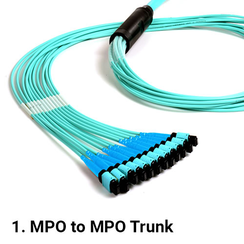
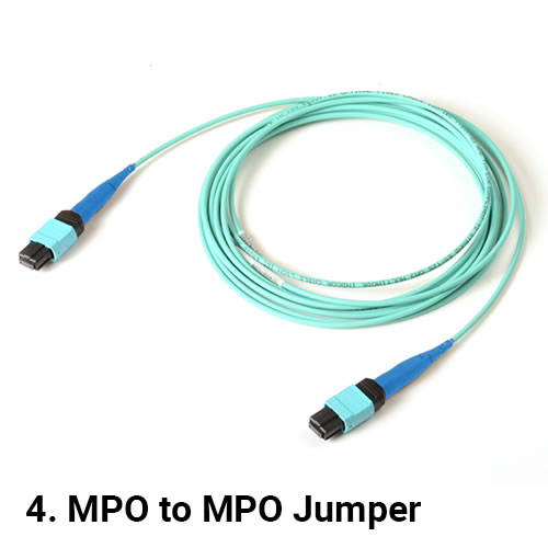
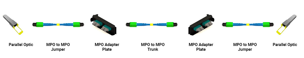
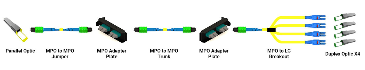
Our own Gary Bernstein makes a lot of sense in his tech brief entitled “The Road to 400/800G is Paved!” As he points out, enterprise data centers are currently running 1G or 10G server speeds and 10G or 40G uplink speeds and are looking at migration paths for 25G or 50G for servers and 100G or 400G for uplinks. Perhaps a step further ahead, cloud data centers currently at 10G to 25G for servers and 40G or 100G for uplinks are actively eyeing server speeds to 50G or 100G with 200G or 400G uplinks. I encourage you to read Gary’s brief to get the full background detail, but the bottom line from a fiber cabling standpoint is that Base-8 fiber topologies leveraging MTP connectivity is the best solution to ease migration to 400G, 800G and beyond.  In other words, Base-8 fiber paves the road to future speeds.

But there are considerations and choices to be made before you even leave the garage.  You need to consider your current needs.  The most efficient fiber cabling and connectivity infrastructure design to support the 10G server and uplink speeds you need right now will not be exactly the same as what you will need to run 100G server speeds and 400G uplinks down the road.  You can make migration easier by installing high-performance, Ultra Low Loss OM4 multimode and singlemode fiber and leveraging Base-8 MTP assemblies wherever practical, but ultimately there’s a good chance that you will need to modify your connectivity when the time comes to trade up to higher speeds.

With a bit of planning while still “in the garage”, you can handle those eventual connectivity reworks without having to tear out half of your fiber infrastructure.  The key piece here is the physical fiber connectivity support system – specifically the fiber enclosures and panels.

For example:  Right now, traditional fusion-splice LC duplex connectivity might be the most efficient, cost-effective solution for your 10G channels, so you select a fiber enclosure well suited to fusion splicing.  Will that enclosure be capable of supporting higher-speed connectivity like Base-8 MTP modules or adapters when the time comes to upgrade?   If the answer is no, then that enclosure will eventually need to be ripped out and replaced – a disruptive and expensive prospect that, hopefully, you would like to avoid.

If your initial answer is yes, then ask yourself if that enclosure will make your upgrade easy. What compromises might you need to accept in converting an enclosure best suited to fusion to support MTP plug and play?  This is the time consider the physical elements like mounting provisions for modules and adapters, configurable cable management, high-volume cord routing, and bend radius control – can I easily reconfigure the enclosure to adapt to my next generation of connectivity?  Just as importantly, does it provide the accessibility to make moves, adds, and changes without disrupting your surrounding infrastructure?

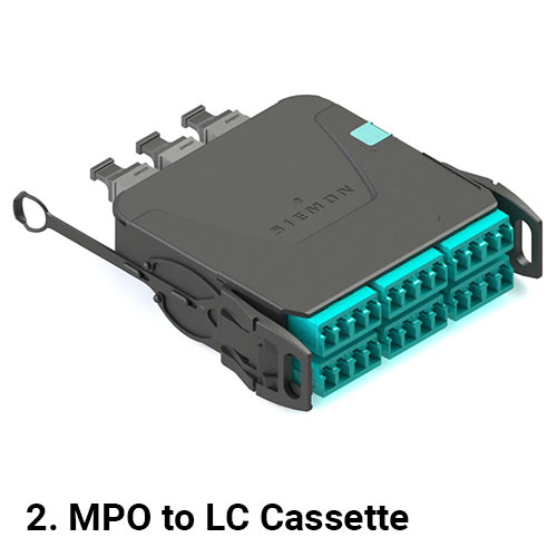
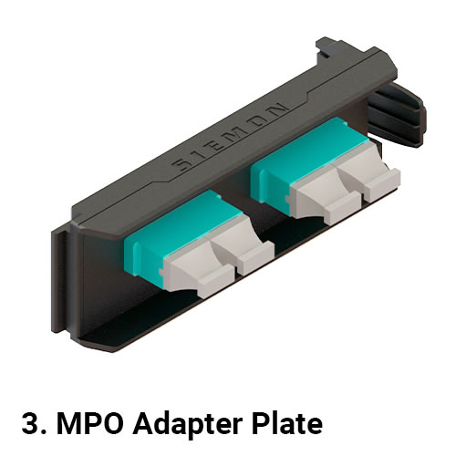
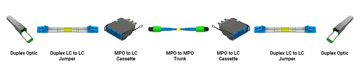
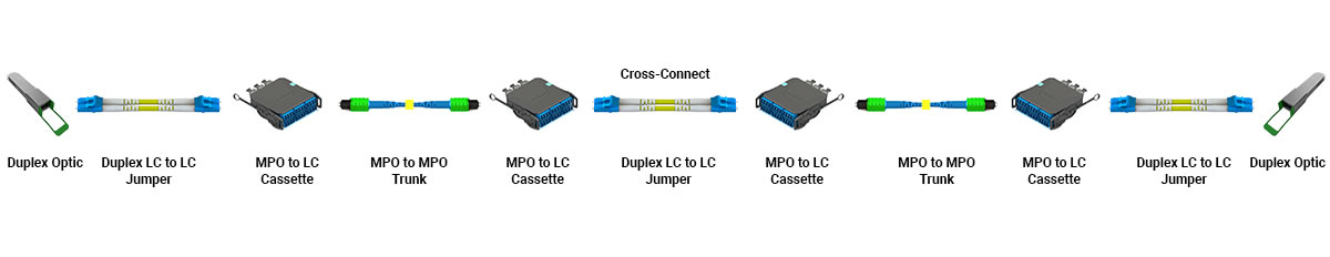
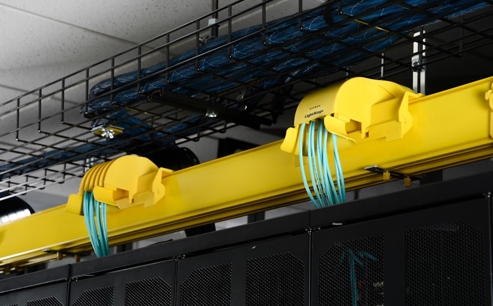
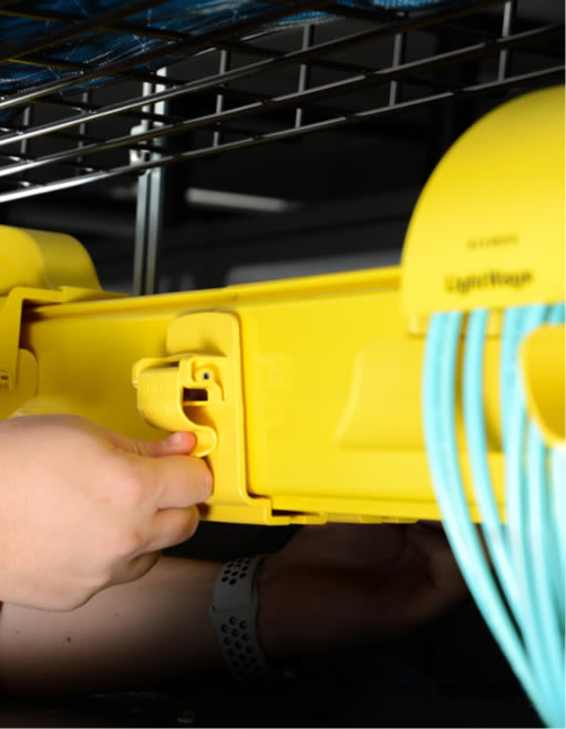
The first piece of good news here is that by even including physical fiber connectivity support infrastructure like enclosures in your future upgrade considerations, you are ahead of the game. The second is that there are highly adaptable, scalable fiber enclosures available. Siemon’s new LightVerse® platform, for example, offers a core set of enclosures all capable of supporting traditional splice trays, pre-terminated splice cassettes, MTP-to-LC duplex plug and play modules, LC duplex adapters, and MTP-to-MTP pass-through adapters.  Paired with highly customizable cable and cord management options, these configurations can be easily modified to fit each unique migration path – even in mix and match situations.  Add in the enhanced accessibility of front and rear sliding trays/drawers and a removeable cover you will find that your future connectivity upgrades can be done more or less on the fly.

To learn more about LightVerse’s innovative, flexible approach to connecting your current and future fiber cabling needs, visit: LightVerse®

Take a deep-dive into the applications, trends and technologies driving the adoption of 400/800G as well as key industry insights that will help you prepare your own organization for the road ahead by visiting The Journey to 400G and 800G has Begun.

  Category: Fiber
  Comments: Comments Off on What To Consider Before Hitting the Road to 400/800G

Why use Plug and Play Fiber Optic Cabling?

By Dave Fredricks,

Plug and Play is a term that has been used to describe a product or solution that works seamlessly when the specific components are connected or plugged together. These words were first used as a feature of a computer system by which peripherals were automatically detected and configured by the operating system. The term has been readily adopted by the cabling industry to describe fiber optic structured cabling links used in the data center and links connecting into the data center space. So what is Plug and Play cabling?

Plug and Play fiber optic cabling contains six basic components that are interchangeable and connect together to make a link. They are: 1. MPO-to-MPO trunk 2. MPO-to-LC cassette 3. MPO adapter plate 4. MPO-to-MPO jumper 5. LC-to-LC jumper and 6. MPO-to-LC equipment cord. The main component of Plug and Play is the MPO-to-MPO trunk which connects together the other five parts that will ultimately connect into the computing equipment. See figure #1.

Figure #1

1MPOTrunk
2MPOCassette
3MPOAdapter
4MPOJumper
5LCJumper
6MPOLCCords


All computing equipment has transceivers or optics that the fiber optic cabling plugs into to complete the connection. There are many types of transceivers or optics available and new types are being released every year. As these new optics are released into the market different types of cabling and connectors are required to make a proper working connection. Another consideration is what type of fiber will be needed in the link – either multimode or singlemode. As these two types of fiber cannot be connected together in a Plug and Play link one needs to be chosen. General parameters of speed and distance help to choose which type of fiber to use. OM4 multimode fiber is typically used for up to 100Gb/s speeds at distances up to 100 meters, while singlemode fiber is used for speeds and distances above 100Gb/s and 100 meters.

Once the fiber type is determined, next is what type of optics will be connected on each end of the link. There are two basic optic types: duplex or parallel. Duplex optics utilize two fibers with one fiber transmitting and one fiber receiving with LC connectors being the most common duplex connector. Parallel optics use eight or sixteen fibers with four or eight fibers transmitting and four or eight fibers receiving with an MPO connector. This is where the Plug and Play link shows its value in that it can support both duplex and parallel optics in a link. As computing equipment refreshes and different optics are used, having the ability to connect them into the existing MPO-to-MPO trunk saves time, labor and money in moves, adds and changes.

A typical duplex Plug and Play deployment has an MPO-to-MPO trunk with MPO to LC cassettes on each end. From the MPO-to-LC cassettes LC jumpers plug into the front of the cassettes and then into the duplex optics as shown in figure #2.

Figure #2

Figure 2

A cross-connect can be added into the link to best serve medium to large data centers with different generations of computing equipment. With a cross-connect design, an active port from a spine, director or core switch can be moved out into the data center space one port at a time. This design helps minimize unused ports so as not to have active ports where they aren’t being utilized or plugged into as shown in figure #3.

Figure #3

Figure 3

The above two Plug and Play links are for duplex or LC optics like the 400GBASE-FR4. With the release of 400G and the soon to be released 800G speeds, singlemode parallel optics are a popular choice for distances of 500 meters or less. This optic is known as 400GBASE-DR4. This 500 meter distance limitation fits into most data center applications.

A typical parallel Plug and Play deployment has an MPO-to-MPO trunk with MPO adapter plates on each end. From the MPO adapter plates MPO jumpers plug into the front of the adapter plates and then into the parallel optics as shown in figure #4. A cross-connect can also be used with parallel optics as it does with duplex optics. Note that customers can readily migrate from duplex applications to parallel applications by removing the MPO-to-LC cassettes and replacing them with MPO adapter plates. This migration is why it’s recommended to use Base-8 components verse Base-12 as the Base-8 option provides use of all fibers in the MPO-to-MPO trunk after the conversion from duplex to parallel links.

Figure #4

Figure 4

With Plug and Play there is an option to breakout one parallel optic into four duplex optics. For instance, this happens with both Ethernet and Fibre Channel links like 100 Gb/s to 4x 25 Gb/s and 128 Gb/s to 4x 32 Gb/s, respectively. Again, the main component is the MPO-to-MPO trunk. On both ends is the MPO adapter plate. On one end is an MPO jumper into the parallel optic and on the other end is an MPO-to-LC equipment cord with four LC connectors plugging into the four duplex optics as shown in figure #5. Plug and Play supports three types of links: duplex-to-duplex, parallel-to-parallel and parallel-to-duplex.

Figure #5

Figure 5

As mentioned at the beginning, Plug and Play has six basic components. The MPO-to-MPO trunks are built to the length of the application and are available in fiber counts of 8 to 144. It is recommended that the MPO trunks are built as Base-8 with Method B polarity to best support duplex and parallel optics. It is also recommended that the MPO trunks have pinned (pinned) connectors so they can plug into MPO jumpers which are non-pinned (unpinned). The MPO-to-LC cassettes that plug into the MPO trunk are also non-pinned (unpinned) to plug into the MPO trunk and built with Type B polarity. The MPO jumpers as non-pinned (unpinned) can also directly connect two parallel optics using Type B polarity. LC to LC jumpers are type A-to-B and will plug together two duplex optics. The MPO-to-LC cords are also non-pinned (unpinned) and will plug into the MPO trunk and breakout a parallel optic into four duplex LC connections.

Once the Plug and Play cabling components are selected, adding new links is easily repeated by stocking basic hardware components like enclosures, MPO-to-LC cassettes, MPO adapter plates, MPO and LC jumpers. As the MPO trunk lengths can change depending on the distance of the link they can be purchased with quick ship programs.

Siemon has just released a quick ship program called FiberNOW that contains all the needed components in a Plug and Play solution for quick and speedy deployment.

  Category: Fiber
  Comments: Comments Off on Why use Plug and Play Fiber Optic Cabling?

Are Supply Chain Issues and Extended Fiber Cabling Lead Times Delaying Your Network and Data Center Projects?

By Tony Walker,

2021-11-supply-chain

2021-11-supply-chain

Despite the global economy slowly starting to recover, one rather destructive issue left in the wake of the waning Covid-19 pandemic is the major disruption to the global supply chain. Previously existing inefficiencies in the supply chain have been compounded by border restrictions, labor and material shortages, skyrocketing demand following lockdowns, weather events, and geopolitical factors (just to name a few) that have left bottlenecks in every link of the supply chain – all while driving prices and lead times to all-time highs. The Institute for Supply Management’s latest survey of purchasing managers shows that the average lead time for production materials increased from 15 days to 92 days in the third quarter this year, the highest levels seen since 1987.

While many of the containers piling up in ports contain consumer goods, the information communications technology industry is certainly not immune to this crisis—especially considering the shortage on raw materials, chips, capacitors, and resistors used in network equipment and sub-component assemblies. With many planned upgrades put on hold at the onset of the pandemic now ready to ramp up, data center and network infrastructure owners and operators are increasingly frustrated by long lead times that hinder the very thing that Covid-19 accelerated—the hunger for more information and connectivity.

In the face of these challenges, leading industry manufacturers are innovating to maintain resiliency and meet customer expectations by diversifying suppliers and reducing reliance on overseas sources, as well as implementing advanced inventory management strategies such as increased forecasting, localizing production, and expanding distribution plans. At Siemon, we’re taking it one step further with guaranteed expedited shipping on mission critical fiber cabling solutions through our FiberNOW™ fast ship program.

Leveraging new advances in logistics and adding extensively to Siemon’s already best-in-class ISO 9001 manufacturing and warehousing capabilities, FiberNOW’s extensive list of multimode and singlemode fiber cabling and connectivity products are guaranteed to leave our facility in or less 5 days – including both standard and custom configurable options!

FiberNOW solutions include plug-and-play LC and MTP OM4 and OS2 jumpers and trunks, MTP-LC assemblies, cassettes, modules, and enclosures—everything today’s network data center owners and operators need to deploy 10 to 400 Gigabit switch-to-switch and switch-to-server links. The FiberNOW solution allows new services and applications to be deployed quickly to meet the ever demand.

Instead of being frustrated with supply chain issues and long lead times that are delaying your data center network upgrades and expansions, get the fiber you need now with Siemon’s FiberNOW program.

Learn more: FiberNOW™ – Fast Ship Program

  Category: Data Center, Fiber
  Comments: Comments Off on Are Supply Chain Issues and Extended Fiber Cabling Lead Times Delaying Your Network and Data Center Projects?

Is OM5 Fiber a Good Solution for the Data Center?

By Gary Bernstein,

OM5 Fiber

OM5 FiberI created a blog on this topic back in April 2017…this content is updated with current standards and applications…but it is still very much true today…4 ½ years later…Make sure you work with people & companies you can trust that have your best interests in mind.

Wideband Multimode fiber (WBMMF) was introduced as a new fiber medium in ANSI/TIA-492AAAE, in June 2016. The ISO/IEC 11801, 3rd edition standard is now using OM5 as the designation for WBMMF. OM5 fiber specifies a wider range of wavelengths between 850 nm and 953 nm. It was created to support Shortwave Wavelength Division Multiplexing (SWDM), which is one of the many new technologies being developed for transmitting 40 Gb/s, 100 Gb/s, and beyond.

OM5 is being presented as a potential new option for data centers that require greater link distances and higher speeds. However, many enterprise IT and data center managers are increasingly adopting Singlemode fiber systems to solve these challenges.

So, what are the reasons a data center might consider installing OM5?

“OM5 offers a longer cabling reach than OM4.”

The difference is minimal.

For the majority of current and future Multimode IEEE applications including 40GBASE-SR4, 100GBASE-SR4, 200GBASE-SR4, 400GBASE-SR8 and future 400GBASE-SR4, the maximum allowable reach is the same for OM5 as OM4 cabling. There are only 3 current Ethernet applications that state an additional 50 meter reach with OM5. If a data center is using non-IEEE-compliant 100G-SWDM4 or BiDi transceivers, they would see a 150-meter reach with OM5 – only 50 meters more than OM4. For most cloud data centers, if they have cabling runs over 100 meters, they will likely use Singlemode for 100 Gb/s and greater speeds. Additionally, any installed OM5 cabling beyond 100m may be limited in its ability to support of future non-SWDM applications.

“OM5 will reduce costs.”

It won’t.

OM5 cabling costs about 30-40% more than OM4. In addition, if you look at the cost of a full 100 Gb/s channel, including BiDdi transceivers, the amount per channel is still 40% more than a 100GSR4/OM4 channel. The costs of Singlemode transceivers have declined considerably over the past 12-18 months due to silicon photonics technologies and large hyperscale data centers buying in large volumes. When comparing the price of 100 Gb/s transceivers, 100G-PSM4 using Singlemode fiber is the same price as 100GBASE-SR4 using Multimode fiber.

“OM5 is required for higher speeds.”

Not true.

All of the current and future IEEE standards in development for 100/200/400/800 Gb/s will work with either Singlemode (OS2) or Multimode (OM4). The majority of these next-generation speeds will require Singlemode. IEEE always strives to develop future standards that work with the primary installed base of cabling infrastructure so customers can easily migrate to new speeds. The latest draft of IEEE P802.3db standard includes 400GBASE-SR4 (a lower cost, less complex, more attractive alternative to 400GBASE-SR4.2) which will have the same reach for OM4 & OM5.

“OM5 will create higher density from switch ports.”

It won’t.

It has very been common for data centers using 40GBASE-SR4 and 100GBASE-SR4 to increase port density by breaking out 40 or 100 Gb/s ports into 10 or 25 Gb/s channels. If a data center manager decides to use SWDM4 or BiDdi modules with OM5 cabling, they cannot break out into 10 or 25 Gb/s channels. This is a major disadvantage of using this technology.

“Do the leading switch manufacturers recommend using OM5 cabling with their equipment?”

No, they show OM3 & OM4

Example from Cisco: “In 40-Gbps mode, the Cisco QSFP 40/100-Gbps BiDi transceiver supports link lengths of 100 and 150 meters on laser-optimized OM3 and OM4 Multimode fibers, respectively. In 100-Gbps mode, it supports 70 and 100 meters on OM3 and OM4, respectively.” Example from Arista: “100GBASE-SWDM4: Up to 70m over duplex OM3 Multi-mode fiber or 100m over duplex OM4 Multi-mode fiber”

Siemon does not see any good reason to currently recommend OM5 to large data center operators. For enterprise data centers looking at migrating to 40GBASE-SR4 or 100GBASE-SR4, OM5 offers no additional benefit over OM4. And larger cloud data centers are either already using Singlemode or planning to move to Singlemode in the near future for migration to 800 Gb/s and 1.6 Tb/s without changing out their cabling.

Learn more about Siemon’s Multimode and Singlemode solutions.

View webinar: Siemon TechTalk | What Are The Real Benefits of OM5?

  Category: Data Center, Fiber
  Comments: Comments Off on Is OM5 Fiber a Good Solution for the Data Center?

The importance of protecting fiber optic cabling infrastructure

By Christopher Homewood,

The importance of protecting fiber optic cabling infrastructure

LightWays Fiber Routing System

The number of optical fiber links between switches, storage area network (SANs), and equipment continue to rise in data center environments due to increasing data and bandwidth needs. As connections between core, SAN, interconnection, and access switches push to 50, 100, 200 or higher gigabit per second (Gb/s) speeds and require low-latency transmission to effectively manage larger volumes of data, fiber is emerging as the dominant media type for data center infrastructure. As the flexibility, scalability, and higher bandwidth offered by fiber continues to lead to the replacement of copper cables across the data center, market volume for fiber is expected to increase at a rate of more than one and a half times that of copper in the years ahead.

Copper vs Optical Fiber

As a data center manager, the challenge of routing and segregating increasing amounts of fiber from network distribution to SANs and server areas is always prevalent. You need to ensure those routes maintain fiber protection and cost-effectively facilitate change so that you can confirm optimal performance, uptime, and scalability in your data center.

The Need for Effective Fiber Optic Protection

Fiber is sensitive to stress, and it is imperative to maintain proper bend radius of fiber cable along its entire route-both during and after installation. The bend radius of a cable is the amount of bending the cable can handle before sustaining damage or signal loss that can limit bandwidth performance. When a fiber cable is bent beyond its minimum bend radius, light signals carrying data can leak out at the bend location. Maintaining proper bend radius becomes an even greater concern for higher-speed data center applications that have more stringent fiber loss requirements. Consider that 10 Gb/s Multimode applications have a maximum channel insertion loss of 2.9 dB, while higher-speed, 40, 100, 200, and 400 Gb/s applications have a maximum loss of just 1.9 dB.

The minimum bend radius of fiber cable depends on its diameter, overall construction, and whether or not it’s under tension (i.e., during installation). Generally speaking, the standard minimum bend radius for fiber is 20 times the cable diameter under tension and 10 times the diameter after installation. Maintaining the minimum bend radius can be especially difficult when routing fibers through cable managers in higher-density, tight spaces within racks and cabinets. While newer bend-insensitive fiber that is less susceptible to performance loss from bending can ease the burden by offering a greater bend radius of 15 times the diameter under tension, you still need to pay close attention to bend radius throughout all pathways to achieve maximum performance. Best practice to avoid problems is to select fiber routing systems, cable managers, and connectivity solutions with integrated bend radius protection throughout.

The physical bends that occur in a fiber cable are referred to as macrobends, but they are not the only bends you need to worry about. Small microbends in the fiber caused by pressure on the cable can also cause signal loss. Over time, these microbends can cause the glass to crack and render the fiber completely dark with no ability to pass any light signals, leading to downtime and additional time and money required to locate and repair the break.

macrobend vs microbend

One of the primary causes for microbends is fiber cable resting on a pressure point such as a basket tray rung, hard edge, or other nonconforming surface or transition points. They can also be caused by weight from other cables, which can occur from overloading pathways beyond recommended capacity. Cable routing systems specifically designed for fiber with flat surfaces and no hard edges at transition points go a long way to preventing microbends while also providing a more secure environment.

To prevent the overloading of pathways, you also want to make sure your routing system has plenty of capacity and can be easily updated to support more as your data center grows.

An additional benefit of fiber routing systems over traditional solutions such as wire ducting or basket tray is the additional security and fire protection offered. It’s important than when selecting a solution, that you opt for a halogen-free option, this will provide additional peace of mind that if the worst were to happen that your infrastructure and employees will have maximum protection.

Changing Technology Demands Additional Flexibility and Scalability

With transmission speeds and the number of data center fiber links on the rise, it is also important that your data center’s fiber routing system makes it easy to access the entire route, allowing the addition of new fiber or replacing existing fiber to support new applications. At the same time, the increasing complexity of the overall data center environment may have you facing some additional challenges when it comes to routing fiber between critical areas and equipment.

As new technology and applications emerge and data centers become highly virtualized, switch-fabric mesh architectures (i.e., spine-leaf) that support low-latency networking also mean multiple redundant paths to connect every switch to every other switch. The dynamic nature of highly virtualized data center environments doesn’t just mean more fiber; it also means more fiber routed to more spaces and more equipment. If you’re dealing with a large data center environment segregated into multiple interconnected switch fabrics, you likely know just how complicated fiber routes can be.

Lightways

Maintaining and managing diverse fiber paths in these complex, highly dynamic environments demands routing systems that are flexible and scalable by design to enable reconfiguring existing routes or adding new routes easily and quickly. When it comes to reconfiguring or adding to a routing system, it’s also better to avoid tool-based connections that require drilling and screws as they require more time and incur further labor costs, as well as creating additional dust and debris which is best avoided in these critical environments.

Discover how Siemon’s LightWays can help you protect, segregate, and manage your data center’s ever-increasing and complex fiber infrastructure to ensure maximum performance, uptime, and scalability.

Other recent blogs we think you’ll like:

  Category: Data Center, Fiber, General
  Comments: Comments Off on The importance of protecting fiber optic cabling infrastructure