Category: Intelligent Buildings


Clear the Way for AV over IP!

By bconroy,

Audio Visual Solutions

While the term video over Internet Protocol (IP) has existed for quite some time, it essentially has been used to refer to any type of IP-based video transmission. However, regardless of the cabling medium, most of these systems to date have been supported by traditional audio visual (AV) architectures where signals are sent and received via AV transmitters, receivers and video matrix switches rather than using true Ethernet LAN switches. This has prohibited AV transmission from truly converging onto existing network cabling infrastructures, and they have instead remained on their own standalone network. But all that is changing with AV over IP that uses standard network equipment to transmit and control AV signals.

A Step in the Right Direction

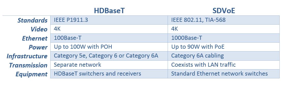
Over the past decade, balanced twisted-pair copper cabling (i.e., Category 6 and Category 6A) has become an AV-supporting medium using baluns that enable composite and analog video to operate over the twisted-pair cabling. The use of AV over twisted-pair cabling really came to fruition in 2010 with the introduction of the HDBaseT standard.

Since it was introduced by the HDBaseT Alliance, HDBaseT has evolved to support what has been dubbed “5Play”—the transmission of ultra-high definition 4K video and audio along with 100 Mb/s Ethernet (100Base-T), USB, bidirectional control signals and 100W of power (power over HDBaseT [POH]) over a single twisted-pair cable for distances up to 100 meters using standard 8P8C (RJ45) connectivity.

While HDBaseT can run over Category 5e (to limited distances) and Category 6 cabling, the HDBaseT Alliance and HDBaseT equipment vendors all recommend the use of Category 6A twisted-pair unshielded cabling at a minimum to support the bandwidth required for 4K signals and reach the full 100-meter distance. Many AV vendors recommend stepping that up to Category 6A or Category 7A shielded twisted-pair cable to ensure a truly robust performance—especially for installations with unmanaged environmental factors. Shielded Category 6A or Category 7A offers better resistance to alien crosstalk, which has a significant impact on HDBaseT signals wherever multiple cable are bundled together. Further, with POH running at a higher remote powering level of 100W, shielded cabling offers far superior heat dissipation and thermal stability.

While HDBaseT remains the most popular AV protocol over twisted-pair cabling and was a step towards using a common cabling medium, it is not true IP as it used a different packetization protocol (T-packets). Further, an HDBaseT system must use HDBaseT equipment, so it essentially must remain as a standalone system and therefore does not meet the true definition of IP convergence.

Embracing Full AV Convergence

Today, there are newer AV protocols that truly can be considered an IP system because they transmit AV signals over standard off-the-shelf Ethernet LAN switches. Introduced in 2017, Software Defined Video over Ethernet (SDVoE) supporting uncompressed 4K video, audio, control and 1 Gb/s Ethernet (1000BASE-T) is one such platform that aims to offer greater saving, flexibility and scalability compared to HDBaseT since it addresses the full 7-layer OSI model and leverages what we in the IT industry already use for transmitting data—standards-based network cabling, Ethernet, TCP/IP and low-latency switching. It also eliminates the use of AV video matrix switches, which typically cost about 90% more per port than a standard Ethernet switch since Ethernet ports are bidirectional and can therefore be used as both an AV input and output port. Ethernet switches also typically take up about a quarter of the rack unit space compared to a video matrix switch, and they support power over Ethernet (PoE) capable of delivering up to 90W of power.

While a few other AV over IP protocols have been introduced, such as the Society of Motion Picture and Television Engineers (SMPTE) 2110 standard that defines the uncompressed transmission of HD video over IP, JPEG-2000 lightly compressed video over IP, and high-efficiency H.264 and H.265 video compression for video over IP, most industry professionals see SDVoE as the most disruptive technology and the one that will ultimately pave the way for fully converged AV over IP. In response, the HDBaseT Alliance introduced HDBaseT over IP shortly after the introduction of SDVoE to also leverage standards-based network infrastructures and 10 Gb/s Ethernet switches for cross-campus transmission, but it requires HDBaseT-to-HDBaseT-IP bridges and HDBaseT-IP switches.

When it comes to network cabling media for SDVoE, Category 6A cabling is not just recommended—it’s required. SDVoE requires a 10 Gb/s Ethernet network (10GBASE-T), which can only be supported by a minimum of Category 6A cable. And for the same reasons as HDBaseT, shielded cabling is recommended—eliminating crosstalk and providing superior heat dissipation and thermal stability for remote powering (PoE in the case of SDVoE).

HDBaseT vs SDVoE

We’ve Got Your AV Cabling System

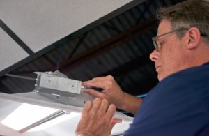
Regardless of whether your AV system is HDBaseT or a true IP solution like SDVoE, Siemon has the cabling systems you need to support it all—and with superior performance to fully combat video disrupting alien crosstalk for a clearer picture. And because Siemon Category 6A and 7A shielded cables offer a higher operating temperature of 75°C for better heat dissipation (exhibiting half the heat buildup of UTP) they offer superior support for the higher power levels of POH and PoE (100 and 90 Watts) needed to power video displays.

Siemon's Z Plug

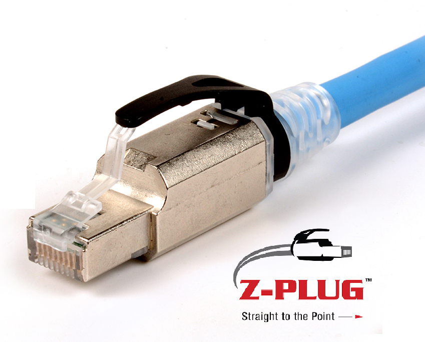
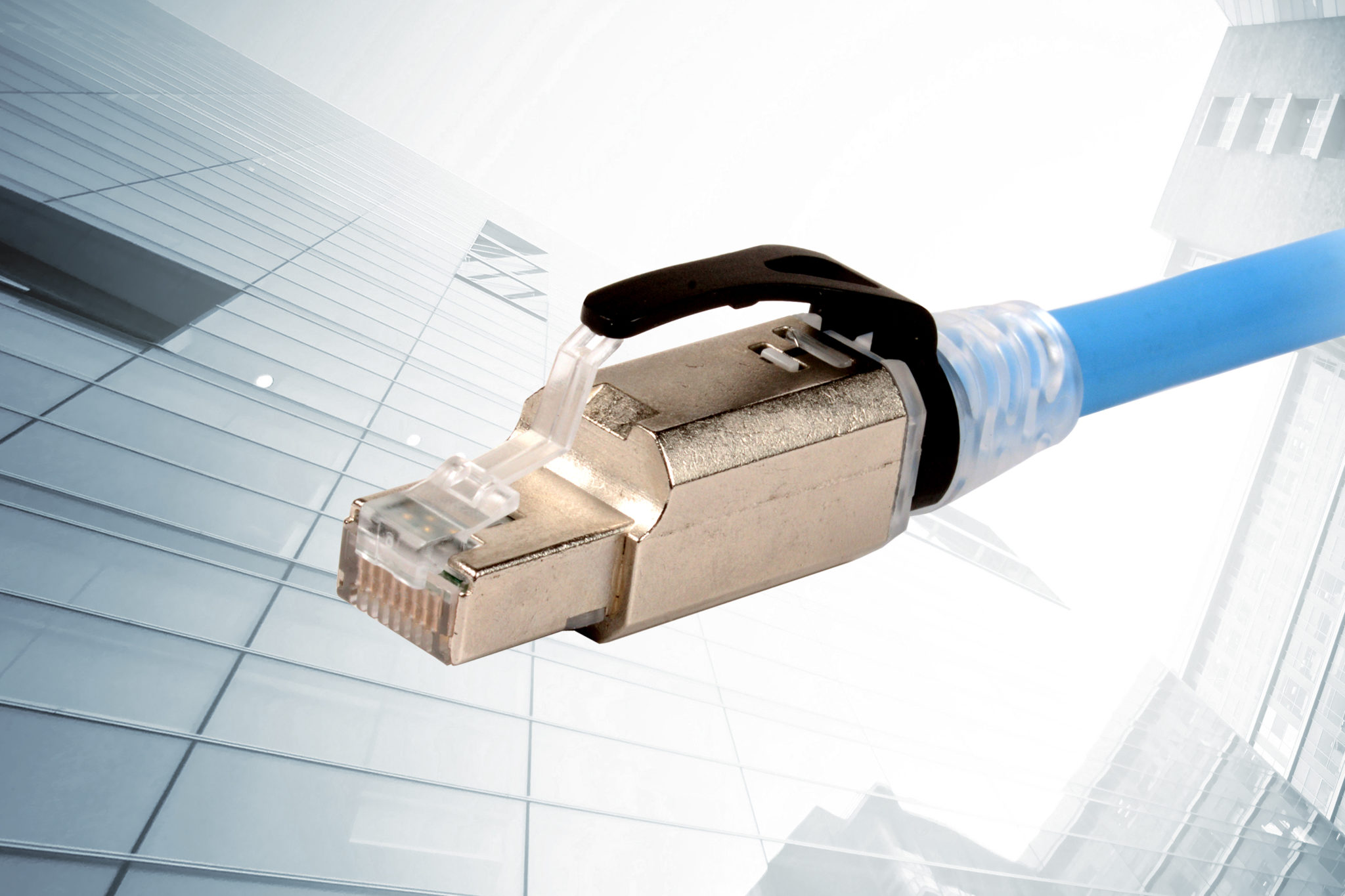
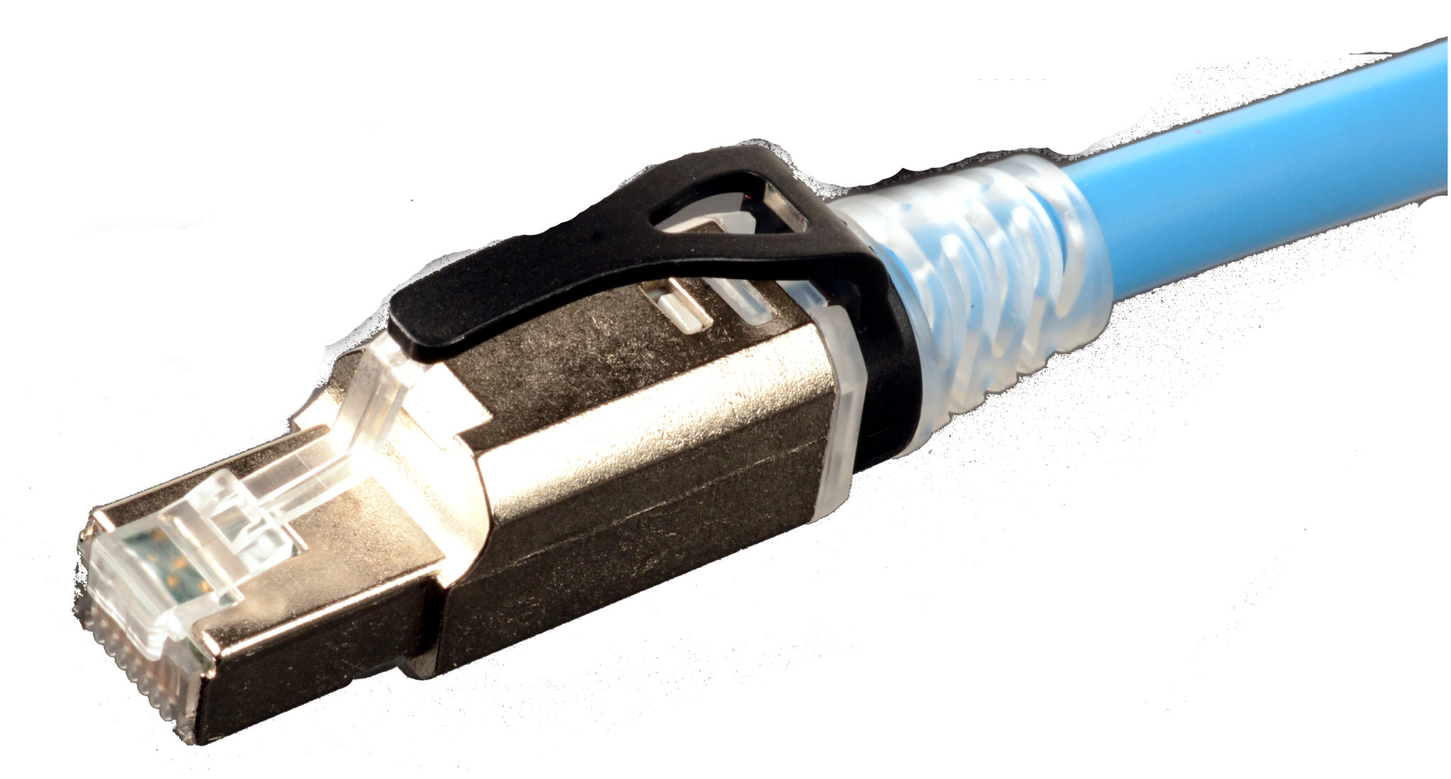
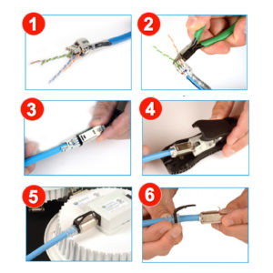
These cables can also both be terminated to our industry-leading Category 6A shielded connectivity, including our robust high-performance Z-PLUG field-terminated plug that allows for custom-length direct connections to video displays, eliminating the need for traditional outlets and patch cords for a cleaner, more aesthetically pleasing look and material cost savings. Click HERE to learn more about our shielded cabling systems and Z-PLUG to support your AV over twisted-pair application.

A New Acronym To Remember

By bconroy,

A New Acronym To Remember

Modular Plug Terminated Link (MPTL)

Our industry is laden with acronyms from AC (alternating current) to ZWP (zero water peak) and everything in between. The newest acronym making its mark on the structured cabling industry is MPTL. It stands for Modular Plug Terminated Link, which refers to terminating the equipment end of horizontal cable with a modular plug to connect directly into a device vs. terminating at an outlet and connecting the device with a patch cord.

You read about it first in our Standards Informant, but you need to know how the MPTL is used and its impact on the structured cabling industry, as it will affect the way we design a network. Channel implementations with an outlet and patch cord are always recommended for equipment connections because they offer more flexibility, support labeling and administration, and eliminate the need to remove long lengths of abandoned cabling should a device be moved. However, sometimes an alternate configuration is necessary, and this new acronym will help advance intelligent building and Siemon’s ConvergeIT initiatives as it provides a new means of connection for the growing number of devices that converge on a unified network infrastructure.

Installing a plug (versus an outlet) on the end of a horizontal cable and plugging directly into an end device is not a new concept, as security camera installers have been doing this since IP cameras came into existence in the late 1990s. The problem is that connecting directly to the device with a plug negates the standards definition of a permanent link, which includes the horizontal cable from the patch panel in the Telecommunications Rooms (TR) to the Equipment Outlet (EO), as well as the definition of a channel, which includes the permanent link and the patch cords on both ends.

Because the MPTL is neither a link or a channel, the main issue is testing and certifying the cable segment?  ANSI/BICSI-005 Electronic Safety and Security (ESS) System Design and Implementation Best Practices followed by ANSI/BICSI-007 Information Communication Technology Design and Implementation Practices for Intelligent Buildings and Premises were the first standard documents to accept the MPTL method and referred to it as a “direct connection.” Their solution for testing this cable segment was to override the testing procedure with a “modified permanent link.”  However, since BICSI standards are primarily design and installation guides, they defer to TIA to provide direction on cable types including testing methodology, but TIA had not specifically addressed testing this connection method. Until recently.

A Standards-Compliant Approach

In July of this year, TIA published ANSI/TIA-568.2-D in which Annex F addresses the testing and acceptance of the MPTL termination method for certain limited cases when an equipment outlet and patch cord are not practical – typically in environments where the device is not often moved or rearranged. In the MPTL configuration, the horizontal cable is terminated at a patch panel in the TR and the device end would is terminated to a plug and connected directly to the device, or it is terminated to a Service Concentration Point (SCP) outlet, typically housed in a  zone enclosure, and from there, the cable is terminated to a plug and connected directly to the device.

MPTL scenarioTo verify the performance of the final plug connection at the far end, the ANSI/TIA-568.2-D standard also includes a new test procedure that includes the final plug connection . It does this using a permanent link adapter at the TR end and a patch cord adapter at the far end where the cable terminated to the plug. The test figure shows the testing configuration (courtesy of Fluke Networks). It’s important to note that the tester you use must have the proper adapters and software to accurately test this MPTL scenario.

Z-PLUG and the MPTL  

The standards’ allowance of the MPTL in certain limited cases and the increasing trend of IP-enabled IB applications is a perfect application for Siemon’s Z-PLUG.

Z-PLUG Field Terminated Plug
The Z-PLUG is robust, easy to field terminate and can withstand repeatable mating and un-mating of devices. Unlike other plugs, Siemon’s Z-PLUG easily terminates to any category 5e, category 6 or category 6A cable – shielded or unshielded, solid or stranded (22 to 26 AWG) – and it meets UL 2043 plenum requirements.

If your customers are designing intelligent building systems, refer to these standards for proper cabling choices, termination and testing, but make sure you always have a Z-PLUG in your back pocket and be prepared to talk about MPTL.

What Type of Cabling Do I Need for the Latest 802.11 Wi-Fi?

By bconroy,

Wi-Fi

In 2013, IEEE published the 802.11ac standard for very high throughput Wi-Fi, which has come to be known as Wi-Fi 5. The appeal of Wi-Fi 5 has fueled broad reaching adoption with steady growth over the past five years, accounting for more than 80% of access point shipments in 2017 and predicted to render previous Wi-Fi 4 (802.11n) products obsolete in enterprise WLAN deployments by the end of this year. And that’s no surprise — by concentrating signals and transmitting over multiple send and receive antennas in the less-crowded 5GHz spectrum, Wi-Fi 5 enables theoretical speeds that are more than 11 times faster than Wi-Fi 4!

Wi-Fi 5 Wave 1 devices hit the market a few years ago and supported speeds of up to 1.3 G/bs, and we are now seeing Wave 2 devices that can support speeds up to about 3.5 Gb/s. If you thought Wi-Fi bandwidth couldn’t get any higher, think again. IEEE is now working to boost Wi-Fi performance even higher with a new high-efficiency standard called Wi-Fi 6.

Targeted towards large public spaces where Wi-Fi 5 simply can’t keep up with the volume of devices (think crowded arenas or busy airports with hundreds of people trying to stream video at the same time), Wi-Fi 6 aims to deliver a single stream at 3.5 Gb/s with the ability to deliver four simultaneous streams for a total of at least 11 Gb/s. We won’t get into the technical details of how Wi-Fi 6 actually works, other than to state that it essentially doubles the streams of Wi-Fi 5 Wave 2 devices and leverages existing LTE cellular technology to further split the streams for four times the effective bandwidth.

Whether you’re just now upgrading to Wi-Fi 5, or already looking to deploy Wi-Fi 6, when it comes to choosing the cabling type to connect the latest 802.11 Wi-Fi access points, it should be category 6A shielded cabling or higher – hands down. And here are the top 3 reasons why:

1. Category 6A cabling is recommended by industry standards

TIA specifically states “Cabling for wireless access points should be balanced twisted-pair, category 6A or higher, as specified in ANSI/TIA-568-2.D, or two-fiber multimode optical fiber cable, OM3 or higher, as specified in ANSI/TIA-568-3.D.”

2. Category 6A cabling is the only way to achieve > 5 Gb/s throughput

Deploying two category 6A channels to access points is the only way to achieve multi-1 Gb/s link aggregation needed for immediate support of 1.3 Gb/s to 3.5 Gb/s 802.11ac Wave 1 and Wave 2 implementations, as well as multi-10 Gb/s link aggregation for future Wi-Fi 6 high-efficiency implementations. Learn more.

3. Category 6A shielded cabling is the best option for powering access points

The majority of 802.11 Wi-Fi access points are powered via power over Ethernet (PoE). Only category 6A shielded cabling or higher exhibits the heat dissipation and thermal stability to reduce length de-rating and bundling restrictions. Otherwise, you may need to reduce your channel length and bundle sizes to avoid increased insertion loss that can impact performance. Learn more.

There are additional cabling considerations to maximize performance and manageability of Wi-Fi 5 and Wi Fi 6 deployments, such as use of a zone cabling design methodology, plug-terminated links, solid conductor cords and higher temperature rated cables.

Stay tuned for more information on optimizing your next-generation Wi-Fi.

  Category: Intelligent Buildings
  Comments: Comments Off on What Type of Cabling Do I Need for the Latest 802.11 Wi-Fi?

Straight to the Point: Siemon’s New Z-PLUG Delivers High-Performance Plug-Terminated Links for Intelligent Buildings

By Brian Duval,

Network infrastructure pros are well aware of the revolution happening inside the walls and ceilings of modern buildings, and they know what is driving it.  It’s the advent of intelligent buildings – the Internet of Things – where virtually every device is connected to the network cabling infrastructure, allowing building systems to communicate via Internet Protocol.  And thanks to advancements in PoE technology that cabling infrastructure is often expected to go beyond data communications, directly delivering low-voltage power to end devices.

camera In a traditional network infrastructure, horizontal cables terminate to work area outlets, with equipment connections made via double-ended patch cords. While this configuration is very commonly used is intelligent buildings to connect IP devices such as PoE lighting, security cameras, wireless access points, digital displays, and building automation controls, it is not always the most efficient method.

This “straight to the point” configuration offers a range of potential benefits, such as:

  • Enabling more rapid deployment of IP devices
  • Simplifying project BOMs
  • Cutting products costs
  • Improving security by eliminating patch cords that can be easily disconnected from devices like surveillance cameras.

However, despite the market availability of field-terminable plugs, the wide adoption of plug-terminated links has, to date, been limited by a number of factors – most critically performance limitations and ease of use.  Again, in the simplest terms, these plugs did not perform as well as the traditional outlet and patch cord configurations and were difficult to terminate.

Siemon ZPlugBut today, thanks to innovations such as Siemon’s new Z-PLUG, the benefits of plug-terminated links for high performance, direct connections to IP devices may be realized.

Request a free Z-PLUG sample

In terms of performance, Z-PLUG delivers a high level of 10 Gigabit system transmission performance and supports advanced Power over Ethernet.  In fact, where switching from the traditional outlet and patch cord device connection to a plug-terminated link once forced cabling pros to sacrifice performance, deploying Z-PLUG to eliminate additional outlets and patch cords can actually improve transmission performance and enable more efficient power delivery.

Z-PLUG also delivers excellent flexibility, supporting the most common cabling types and configurations in a single product/part number. Z-PLUG can be quickly terminated to shielded and UTP, solid and stranded Category 6A and Category 6 cables in conductor sizes from 22 to 26 gauge, allowing it to be easily deployed in a wide range of projects and applications.  To further improve usability, all Z-PLUG components can be plenum-rated for use in air handling spaces.

ZPlugtool copyIn addition to application flexibility, the Z-PLUG’s innovative termination process significantly reduces termination time while simultaneously helping ensure repeatable connection performance. This contractor-friendly, intuitive termination process centers on Siemon’s hand-held, ergonomic Z-PLUG tool.  The steps are extremely simple:

ZPLUG Installation

  1. Strip the outer cable jacket and lay the conductors into the Z-PLUG lacing module
  2. Lace the conductor pairs according to the integrated color-coding guides and trim
  3. Insert the laced module into the plug housing
  4. Insert the plug assembly into the Z-TOOL and finalize the termination in one easy motion
  5. Plug into your IP device!
  6. Z-PLUG can be disassembled and reterminated up to three times

Z-PLUG can be terminated with or without the optional boot.  Coupled with the plug’s rounded corners and reduced-length plug body, Z-PLUG’s ability to “go bootless” make it ideal for connecting devices with limited plug space and depth, such as IP cameras and WAPs.

Other unique features include an optional latch guard that protects the latch during cable routing, provides improved accessibility when unplugging/connecting devices in tight spaces, and supports simple color coding of links through 9 different colors options.

The exponential growth of intelligent buildings and PoE device technology presents an excellent opportunity for network infrastructure professionals: the technology is established, the devices exist, and the volume of network cables needed to support this trend will increase. As such, Z-PLUG’s simple and straight to the point approach to IP end-device connectivity can be a significant advantage.

  Category: Intelligent Buildings
  Comments: Comments Off on Straight to the Point: Siemon’s New Z-PLUG Delivers High-Performance Plug-Terminated Links for Intelligent Buildings

Learn How to Plan and Design for the Future of Smart Lighting

By bconroy,

POELighting

As intelligent lighting systems continue to see substantial growth year after year, it’s beneficial for infrastructure designers to have a comprehensive understanding on the deployment and installation of these systems. In fact, Power over Ethernet (PoE) lighting currently illuminates over one billion square feet of commercial space globally, and it is estimated the number of smart lighting deployments will grow from 46 million units in 2015 to 2.54 billion in 2020!

The driving factors behind its increasing popularity include the ease and benefits that accompany using Ethernet communication for control and deploying remote powering technology, such as 60-watt PoE. These PoE lighting systems rely on a well-designed infrastructure of high performance balanced twisted-pair cabling, network electronics, and software connecting and communicating with Internet Protocol addressable luminaires, dimmers, sensors, and controllers to deliver maximum performance.

PoE lighting luminaires typically use light emitting diode (LED) technology, which offers the added benefits of lower power consumption and less heat generation than other luminaire design alternatives, while lowering capital lighting investment, improving safety and comfort, and integrating with all Internet of Things (IoT)-enabled building automation systems.

A wide range of expertise is needed to specify, install and manage the many components in a PoE lighting system. Zone cabling is ideally suited for these deployments and infrastructure designers should be knowledgeable and prepared to adapt this cost-effective and efficient standards-based design.

Siemon’s newly created guide: Zone Cabling and Coverage Area Planning Guide: 60W PoE Lighting Applications is a valuable tool for designers and architects to utilize when planning PoE lighting systems within highly automated building spaces. This guide covers the areas of design and deployment, installation recommendations, integration with IoT applications, zone cabling for PoE lighting, coverage areas, location of zone enclosures, and more.

Learn more about PoE Lighting Applications for intelligent buildings and access the new planning guide at www.siemon.com/poelighting

  Category: Intelligent Buildings
  Comments: Comments Off on Learn How to Plan and Design for the Future of Smart Lighting