BICSI D033 Keeps Up with Smart Buildings

By bconroy,

roadshowThe extensive number and range of networkable devices available for deployment in today’s smart buildings create environments that are safer, healthier, more energy efficient, and more responsive to occupant needs and preferences than ever before. BICSI D033, “Information Communication Technology Design and Implementation Practices for Intelligent Buildings and Premises” is targeted for publication later this year and will identify best practices for integrating diverse applications and devices on the IT network.

Key chapters will address media recommendations, cabling topologies, design considerations for applications supporting both data and power, device density and coverage area sizing, and pathway considerations. Supplemental information related to deploying lighting, digital signage, acoustic and intercom systems, metering and monitoring systems, and other special building applications will also be provided.

The topologies and media referenced in the draft BICSI D033 Standard are based on the horizontal and backbone cabling specifications appearing in TIA-568.0-D and ISO/IEC 11801 1. Structured cabling supporting intelligent building applications in new installations shall be deployed in a hierarchical star topology and consist of a minimum of category 6/class E (category 6A/class EA recommended) balanced twisted-pair, laser-optimized multimode (i.e., OM3, OM4, and OM5) optical fiber, and all forms of singlemode optical fiber cabling.

The draft Standard emphasizes that a zone cabling design, which consists of horizontal cables run from the telecommunications room to a horizontal connection point or HCP (an intermediate connection point that is typically housed in an enclosure located in the ceiling space, on the wall, or below an access floor) provides a flexible infrastructure to accommodate current and future data, voice, building device, and wireless access point connections. Since spare ports are available at the HCP and individual cables only extend from the outlets at the HCP to building devices or outlets, zone cabling systems support rapid reorganization of work areas and equipment and simplify deployment of new devices and applications.

Detailed requirements for sizing and provisioning assist in the design and layout of entrance rooms, equipment rooms, telecommunications rooms, and telecommunications enclosures where cabling and equipment connections are made. Considerations for a wide range of cabling pathways (e.g., cable trays, J hooks and other non-contiguous pathways, conduit, raceways, ducts, poke-throughs and other in-floor systems, and access floors) aid in identifying the optimum pathway infrastructure system for various building system applications.

The key to a successful smart building deployment is the proper planning, design, and deployment of the cabling infrastructure. When published, BICSI D033 will be a valuable resource for intelligent building cabling best practices and the zone-based structured cabling architectures.


  Category: Standards
  Comments: Comments Off on BICSI D033 Keeps Up with Smart Buildings

Fiber Field Terminations in Under 30 Seconds!!

By bconroy,

LightBow_Promo

Fast deployment and superior reliability are of the utmost importance in today’s fiber networks, which is why many data centers deploy plug-and-play preterminated assemblies – especially for high speed 40 and 100 Gigabit applications that require factory-terminated MPO/MTP style connectivity. But many installation scenarios still benefit from the flexibility of multimode and singlemode duplex fiber field terminations.

When it comes to fiber field termination, quality connections are often directly related to the skill level and experience of the technician performing the termination, and verification is a critical step to ensure that the terminated connectors will reliably transmit the signal. For example, dirty fiber end faces and air gaps between fiber end faces can cause insertion loss and return loss that result in degraded network performance, retransmits or even non-functioning fiber links. And because there are far more steps involved in fiber field termination versus using preterminated fiber assemblies, field termination also results in higher labor costs and slower deployments.

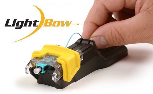
Fiber field termination systems therefore need to offer quick and easy terminations while ensuring consistently high performance connections and the ability to verify that a quality connection has been made. Thankfully, Siemon’s LightBow™ Fiber Termination System provides ALL of these benefits – speed, performance, reliability and the ability to verify the connection.

LightBow’s exclusive patent-pending termination tool dramatically reduces termination time by combining both splice activation and crimping in a single, optimized step and providing universal LC and SC connector compatibility with no time-consuming changeover. It also features integrated LC and SC strip templates molded right into the tool to ensure proper strip length of the fiber. To deliver superior consistent performance, the tool simplifies fiber insertion while its patent-pending bow feature maintains proper pressure of fiber ends during termination to eliminate air gaps. To further ensure reliability, the entire LightBow termination process is completed with the connector dust-cap in place, protecting the critical end face polish from contamination or damage.

And to immediately verify that a quality termination was achieved, LightBow pre-polished mechanical splice connectors feature a built-in verification window in the connector body for use with Siemon’s 0.5mW output power, Laser Class 1 visual fault locator (VFL), which is available in the LightBow Fiber Termination Kit. And following termination verification, the LightBow system offers the unique ability to adjust the fiber or reterminate the connectors if needed.

To showcase the speed and efficiency of the LightBow Termination System, Siemon is hosting a contest available to Certified Installers (CI) in the US, Mexico and Canada from March 1st to July 31st 2017. For this contest, CIs perform a successful termination as quick as possible and submit their recorded times to Siemon via video.  Already, entries show termination times well under 30 seconds!!

Siemon is also offering a FREE LightBow Termination Kit with the purchase of 300 LightBow Connectors. And the kit has EVERYTHING you need for terminations, including the patent-pending tool, the 0.5mW VFL, and a high precision cleaver with a long-lasting blade that lasts for 48,000 cleaves – all in a convenient carrying case.

Check out LightBow.

  Category: Enterprise LANs
  Comments: Comments Off on Fiber Field Terminations in Under 30 Seconds!!

Why 8-Fiber MPO/MTP Solutions Are Your Path of Least Resistance

By bconroy,

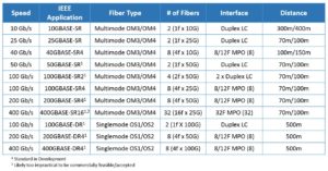
In looking at current and future applications – for both multimode and singlemode – it is easy to see that the foreseeable future will be dominated by 2- and 8-fiber solutions. Table 1 below clearly shows that the Ethernet Optical Transceiver Roadmap includes fiber applications that are always divisible by either 2 or 8 fibers. What does this mean for existing 12-fiber MPO/MTP connections?

Table1_28Fiber

Table 1: Ethernet Optical Transceiver Roadmap includes multimode and singlemode fiber applications that are always divisible by either 2 or 8 fibers

For applications like 40 Gb/s (40GBASE-SR4) and 100 Gb/s (100GBASE-SR4) that are based on 8 multimode optical fibers, as well as future 400 Gb/s, the use of 12-fiber MPO/MTP solutions means that 33 percent of the optical fiber goes unused. One way that data center managers can ensure 100 percent utilization of optical fiber with 12-fiber MPO/MTP solutions is to use conversion cords or modules that transition two 12-fiber or one 24-fiber trunk from backbone cabling to three 8-fiber MPO/MTPs for connecting to 40 and 100 Gb/s equipment. This is ideal for those data centers that already deployed 12-fiber or 24-fiber backbone trunk cables. It should be noted however that conversion modules introduce additional insertion loss into the channel and conversion cords mean that three ports need to be taken off line in the event that the cord needs to be replaced.

On the other hand, 8-fiber MPO/MTP solutions that are starting to hit the market are considered the most efficient option since they support current and future duplex fiber applications using modules that break out 8-fiber MPO/MTPs to duplex LCs, as well as current and future 8-fiber applications without the need for conversion cords or modules.

  Category: Data Center
  Comments: Comments Off on Why 8-Fiber MPO/MTP Solutions Are Your Path of Least Resistance

Singlemode or Multimode for Big Data in the Data Center?

By bconroy,

Data Center cablingThe Internet of Things (IoT) is rapidly evolving and brings many great advantages to organizations. However, the vast amount of Big Data that is expected from IoT, as well as from increasing storage intensive and cloud-based applications, has a significant impact on data centers. Within the data center environment, especially within switch-to-switch backbone links to the core and to the storage area network (SAN), there is immense pressure to handle extreme data volumes. To process this data, switch-to-switch links are rapidly migrating from 10 Gigabit per second (Gb/s) speeds to 40 and 100 Gb/s and beyond, which is best served by optical fiber cabling. In addition to higher speeds, the sheer number of equipment and fiber links continue to increase, leading to increased densities of fiber connections that need to be carefully managed.

With several fiber applications, standards and technologies available, data center managers need to understand current and future choices that provide reliable low latency, high bandwidth connections and scalability. First and foremost, data centers looking to upgrade their entire backbone data center cabling are faced with whether to deploy multimode or singlemode cable. While singlemode may offer the best future proof capabilities, the active equipment required currently remains more expensive than multimode equipment. Further, while most data center backbone links do not require the reach distances currently supported by singlemode fiber, which include up to 10 kilometers (km) for speeds ranging from 40 to 400 Gb/s, hyper scale data center backbone links often exceed the 100-meter maximum link length supported by multimode equipment. Hence, while multimode fiber remains the more common choice for these links, new developments in optimized-reach (i.e., 500 meter) singlemode data center solutions are expected to change the landscape of data center architectures.

Even selecting multimode fiber has become a more complex endeavor, especially with the upcoming 3rd edition of the ISO/IEC 11801 standard that will include a new type of wideband multimode fiber, designated as OM5. While existing OM3 and OM4 multimode fiber is specified to operate in the 840 to 860 nanometer (nm) wavelength range with 850nm as the optimal wavelength, new OM5 wideband multimode fiber specifies a wider range of wavelengths between 840 and 953nm to support wavelength division multiplexing (WDM) technology. WDM technology multiplexes multiple signals onto a single fiber using different wavelengths.

While OM5 may seem like an advantage in terms of reducing fiber strand counts, it is important to note that there are no applications currently under development within the Institute of Electrical and Electronics Engineers (IEEE) to operate over this medium and, as a result, there is no available information on data rate, link length, or strand count for installing this media today. As such, one of the emerging singlemode fiber applications may be the better solution for anyone looking to future proof for 400 Gigabit. For example, the pending IEEE P802.3bs (400GBASE-DR4) standard is slated to cost-effectively support 400 Gb/s over singlemode to 500 meters using 8-fibre MPO/MTP solutions with 4 fibers transmitting at 100 Gb/s and 4 receiving at 100 Gb/s. For more information, see our previous blog on OM5 multimode fiber.

In addition, the pending IEEE P802.3cd (50GBASE-SR) standard – anticipated to release in 2018 – will support single lane 50 Gb/s, demonstrating IEEE’s commitment to the development of higher capacity applications over the installed base of OM3 and OM4 multimode fiber. There is also work on singlemode technologies for shorter reach (500m) applications via the pending IEEE P802.3cd (100GBASE-DR) and IEEE P802.3bs (200GBASE-DR4/400GBASE-DR4) that may provide yet another case for singlemode fiber to be considered.

  Category: Data Center
  Comments: Comments Off on Singlemode or Multimode for Big Data in the Data Center?

Learn How to Plan and Design for the Future of Smart Lighting

By bconroy,

POELighting

As intelligent lighting systems continue to see substantial growth year after year, it’s beneficial for infrastructure designers to have a comprehensive understanding on the deployment and installation of these systems. In fact, Power over Ethernet (PoE) lighting currently illuminates over one billion square feet of commercial space globally, and it is estimated the number of smart lighting deployments will grow from 46 million units in 2015 to 2.54 billion in 2020!

The driving factors behind its increasing popularity include the ease and benefits that accompany using Ethernet communication for control and deploying remote powering technology, such as 60-watt PoE. These PoE lighting systems rely on a well-designed infrastructure of high performance balanced twisted-pair cabling, network electronics, and software connecting and communicating with Internet Protocol addressable luminaires, dimmers, sensors, and controllers to deliver maximum performance.

PoE lighting luminaires typically use light emitting diode (LED) technology, which offers the added benefits of lower power consumption and less heat generation than other luminaire design alternatives, while lowering capital lighting investment, improving safety and comfort, and integrating with all Internet of Things (IoT)-enabled building automation systems.

A wide range of expertise is needed to specify, install and manage the many components in a PoE lighting system. Zone cabling is ideally suited for these deployments and infrastructure designers should be knowledgeable and prepared to adapt this cost-effective and efficient standards-based design.

Siemon’s newly created guide: Zone Cabling and Coverage Area Planning Guide: 60W PoE Lighting Applications is a valuable tool for designers and architects to utilize when planning PoE lighting systems within highly automated building spaces. This guide covers the areas of design and deployment, installation recommendations, integration with IoT applications, zone cabling for PoE lighting, coverage areas, location of zone enclosures, and more.

Learn more about PoE Lighting Applications for intelligent buildings and access the new planning guide at www.siemon.com/poelighting

  Category: Intelligent Buildings
  Comments: Comments Off on Learn How to Plan and Design for the Future of Smart Lighting