Category: Data Center


Data Center Challenges: The Importance of Power, Cooling and Connectivity

By Dave Fredricks,

2021-06-Data-Center-Challenges-feature

Written by Dave Fredricks

2021-06-Data-Center-Challenges-feature

The trend today for data center deployment is to build smaller spaces in more locations closer to the users to reduce latency and increase redundancy, aka Edge Data Centers. This new approach deviates away from past planning of having one or two larger sized enterprise data centers and a secondary disaster recovery (DR) site. The advantages of having more compute assets in multiple locations is obvious but managing these smaller locations can be difficult from a personnel perspective, onsite monitoring and the ability to support current and next generation computing equipment.

The big three components of designing a new data center space are Power, Cooling and Connectivity. Power requirements are addressed initially at the beginning of the process using the need of critical load (power needed at full IT load for all compute equipment) as a value of N. To simplify the number N comes from adding the power needs on a per cabinet basis and totaling all cabinets in the initial build out, plus future growth to obtain power usage or a total power requirement value. Power needs for non-IT compute equipment like cooling and lighting also need to be added. Along with the needed power for the data center space there are different redundancy options to choose from like N+1 or 2N. Once this is calculated the power design is typically static for several years depending on the addition or subtraction of computing equipment in the data center space.

Cooling is a more dynamic aspect of building and managing the data center space. The reason being is as switches, servers and other compute equipment are added or removed in day to day operations this changes the airflow pathways in the cabinets. As the airflow changes in the individual cabinets, it also changes in the entire data center space. Managing the changes is challenging but there are tools available to help. Deploying monitoring sensors throughout the data center space help the operator see in real time the shifts that are occurring and provide feedback on how best to address hot or too cold spots as well as power usage.

Traditionally the monitoring sensors were hardwired into each cabinet and at different locations in the data center space, for instance end of row, underfloor, ceiling plenum spaces and other areas that had temperature considerations. This style of environmental management falls under the category of Data Center Infrastructure Management (DCIM). DCIM is evolving as are many processes in the data center space. Monitoring can now utilize low cost thermal sensors that operate on long-term batteries and wirelessly connect back to the software that is supported with Artificial Intelligence (AI) and Machine Learning (ML). Upsite Technologies offers an AI/ML solution for this application called EkkoSense. This AI/ML technology, while still in its early growth period, offers the ability to have many more data points with inexpensive sensors or input devices providing real time information on all temperature aspects, power usage and PDU utilization of the data center space.

EkkoSense has the ability to display the information provided by the thermal sensors in formats such as 3-D visualization, or digital twin, as shown in figure #1. Other dashboard options are available to view and oversee the entire data center space or sections of the space. These dashboards can be configured to meet the operators thermal and power parameters viewed at multiple locations. The American Society of Heating, Refrigerating and Air-Conditioning Engineers (ASHRAE) sets published standards (90.4-2019, Energy Standard for Data Centers) for the data center industry that set minimum energy efficiency requirements. These requirements can be monitored through EkkoSense and corrective actions can be quickly determined to solve problems as they arise.
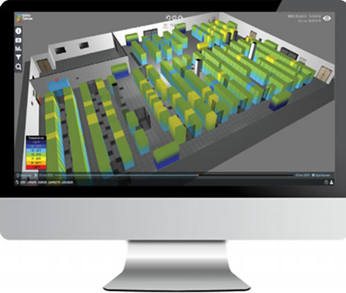
Figure #1

Understanding that often Edge Data Centers are un-staffed and require monitoring 24/7, having a robust platform to monitor the facility is essential. Maximizing the available cold air with proper airflow management and directing hot exhaust air for recirculation will protect the computing equipment. Keeping the computing equipment cool and reducing the cost of energy to its most efficient levels will optimize the running of the data center and reduce downtime from thermal and power failures.

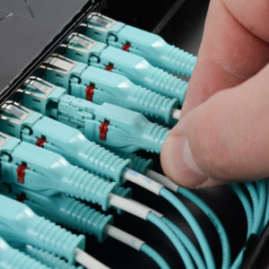
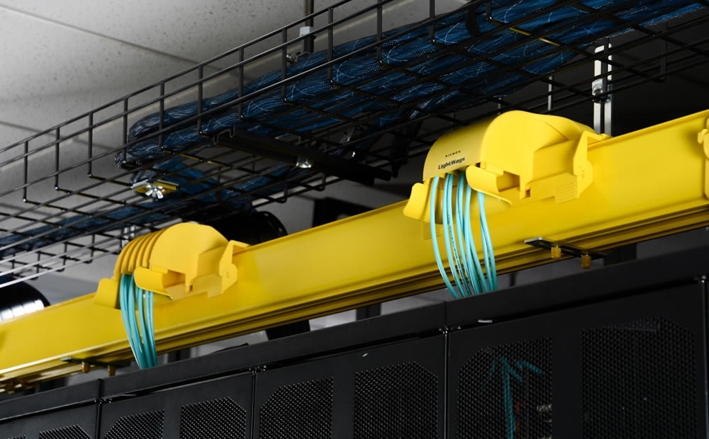
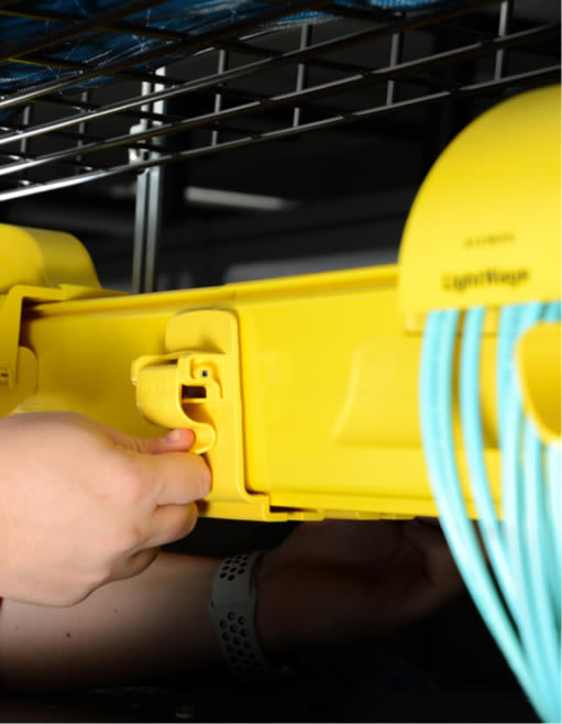
This brings us to Connectivity. Singlemode fiber enters the data center in the Entrance Room. The fiber links are provided by Internet Service Providers (ISP’s) with connectivity to the outside world. Most data centers have at least two ISP connections but often have as many as three to five. From the Entrance Room singlemode fiber runs to individual floors, zones, rooms, pods (group of data center cabinets installed in a rectangular shape for cooling purposes) or cabinets.

Today most new data center deployments have fiber running from cabinet to cabinet and copper connections are in-cabinet or distances less than 5 meters. Often fiber runs under 100 meters use multimode fiber instead of singlemode fiber. The reason is that the optics that plug into the computer equipment with the fiber were traditionally less expensive using multimode fiber. However, over the past 2-3 years the cost of singlemode optics has declined significantly to be near the same cost of multimode optics. This price reduction is in thanks to the large Cloud Providers using all singlemode fiber and optics in their data centers. For this reason, more data center operators are choosing to run singlemode fiber from cabinet to cabinet instead of multimode. Singlemode fiber has an advantage over multimode fiber in that it can support higher speeds, 400G+ over longer distances than multimode. It provides the user with more bandwidth which allows for more interconnects and flexibility in the structured cabling plant.

If you have questions about thermal and power monitoring, whether to deploy singlemode or multimode fiber in your data center or the latest structured cabling designs please reach out to your local Siemon RSM.

Discover how Siemon Advanced Data Center Solutions can help you protect, segregate, and manage your data center’s ever-increasing and complex fiber infrastructure to ensure maximum performance, uptime, and scalability.

  Category: Data Center
  Comments: Comments Off on Data Center Challenges: The Importance of Power, Cooling and Connectivity

Is Your Data Center Keeping Up with Complex High-Density Fiber Links?

By Brian Baum,

2021-04-port-density-cover

Data Centers

Rack space in the data center has long been at a premium, but emerging technologies and an increasing number of applications and amount of data that demand high-bandwidth, low-latency transmission and highly virtualized environments are driving data center complexity and fiber cabling densities to an all-time high-all of which comes with some unique challenges and the need for innovative design and solutions.

Changing Architecture Means More Infrastructure

While fiber density is increasing in the data center due to the sheer amount of equipment needed to support emerging applications and increasing data, it is also being driven by server virtualization that makes it possible to move workloads anywhere in the data center. With increasing virtualization comes the rapid migration from traditional three-tier switch architecture with a north-south traffic pattern to leaf-spine switch fabric architecture with just one or two switch tiers and an east-west traffic pattern.

In a leaf-spine architecture, every leaf switch connects to every spine switch so there is never more than one switch between any two leaf switches on the network. This reduces the number of switch hops that traffic must traverse between any two devices on the network, lowering latency and providing a superior level of redundancy. However, it also increases the overall amount of fiber cabling in the data center. In a leaf-spine architecture, the size of the network is also limited by the number of ports available on the spine switches, and to be completely non-blocking, the sum of the bandwidth of all equipment connections on each leaf switch must be less than or equal to the sum of the bandwidth of all of the uplinks to the spine switches.

2 Tier Leaf-spine architecture

For example, if a leaf switch has thirty-two 10 Gbps server ports (i.e., 320 Gbps capacity), it will need a single 400 Gbps uplink, two 200 Gbps uplinks, four 100 Gbps uplinks, or eight 40 Gbps uplinks to be completely non-blocking. It’s easy to see how the number of fiber uplink connections is increasing!

Optimizing Port Utilization

To help maximize space, maintain low latency, and optimize cost, the use of link aggregation via break-out fiber assemblies is on the rise. It’s not uncommon to find enterprise customers leveraging a single 40 Gbps switch port on a leaf switch to connect to four 10 Gbps servers. As switch speeds increase, link aggregation will offer even greater port utilization and workload optimization.

mtp to lc hybrid assemblies

In January of 2020, the ratification of IEEE 802.3cm for 400 Gbps operation over multimode fiber includes 400GBASE-SR8 over 8 pairs and 400GBASE-SR4.2 over 4 pairs using two different wavelengths. These applications have broad market potential as they enable cost-effective aggregation with the ability to connect a single 400 Gbps switch port to up to eight 50 Gbps ports. With the introduction of full duplex applications like 50GBASE-SR and short wave division multiplexing that supports 100 Gbps over duplex fiber via the pending IEEE P802.3db, MTP-to-LC hybrid assemblies will be essential.

Some data centers also employ link aggregation at the leaf-spine connection to maximize port utilization. For example, rather than using four 100 Gbps ports on a spine switch to connect to a 32-port 10 Gbps leaf switch in a non-blocking architecture, a single 400 Gbps port can be used. However, data center designers strive to carefully balance switch densities and bandwidth needs to prevent risky oversubscription and costly undersubscription of resources at every switch layer.

While oversubscription is not considered completely non-blocking, it is rare that all devices would be transmitting simultaneously so not all ports require maximum bandwidth at the same time. Certain applications can also risk some latency. Oversubscription is therefore commonly used to take advantage of traffic patterns that are shared across multiple devices, allowing data center operators to maximize port density and reduce cost and complexity. Network designers carefully determine their oversubscription ratios based on application, traffic, space, and cost, with most striving for ratios of 3:1 or less between leaf and spine layers.

For example, if we go back to the example of a leaf switch with thirty-two 10 Gbps ports (320 Gbps capacity), instead of undersubscribing by using a 400 Gbps uplink, it may make sense to use a 200 Gbps uplink to the spine switch with an oversubscription ratio of 320:200 (8:5), which is still considered a low oversubscription ratio. This allows a single 400 Gbps port on the spine switch to now support two leaf switches.

leaf switches

While these practices are ideal for switch port utilization, they can make for more complex data center links. That combined with an overall increased amount of fiber means patching areas between leaf and spine switches are denser than ever. In a very large data center, we could be talking about a patching area that encompasses multiple cabinets and thousands of ports for connecting equipment. Think of a meet-me room in a colocation where large cross-connects are used to connect tenant spaces to service providers, or a cloud data center where thousands of switches connect tens of thousands of servers. Not only is that a lot of ports to manage, but it’s also a lot of cable in pathways and cable managers.

Managing It All

In ultra high-density fiber patching environments, accessing individual ports to reconfigure connections can be very difficult, and getting your fingers into these tight spaces to access latches for connector removal can cause damage to adjacent connections and fibers. This is of particular concern when deploying an interconnect scenario that can require accessing critical connections on the switch itself-the last thing you want to do is damage an expensive switch port while trying to make a simple connection change or inadvertently disconnect the wrong or adjacent connection(s). At the same time, the implementation of various aggregation schemes and links running at higher speeds means that downtime could impact more servers. That makes it more critical than ever to maintain proper end-to-end polarity that ensures transmit signals at one end of a channel match receivers at the other end.

Thankfully, cabling solutions have advanced to ease cable management and polarity changes in the data center. For parallel optic applications in switch-to-switch links like 8-fiber 200 and 400 Gbps, Siemon uses a smaller RazorCore™ 2mm cable diameter on 12- and 8-fiber MTP fiber jumpers. To save pathway space between functional areas of the data center, Siemon also uses smaller-diameter RazorCore cabling on MTP trunks. Siemon multimode and singlemode MTP jumpers, trunk assemblies and hybrid MTP-to-LC assemblies also feature the MTP Pro connector that offers the ability to change polarity and gender in the field. (read more about the MTP Pro and polarity.)

LC BladePatch® Fiber Jumpers

For duplex connections, Siemon’s LC BladePatch® jumpers and assemblies offer a smaller-diameter uni-tube cable design to reduce pathway congestion and simplify cable management in high-density patching environments. Available in multimode and singlemode, the small-footprint LC BladePatch offers a patented push-pull boot design that eases installation and removal access, eliminating the need to access a latch and avoiding any disruption or damage to adjacent connectors. LC BladePatch also features easy polarity reversal in the field.

In fact, Siemon recently enhanced the LC BladePatch with a new one-piece UniClick™ boot that further reduces the overall footprint to better accommodate high-density environments and makes polarity reversal even faster and easier. With UniClick, polarity reversal involves just a simple click to unlock the boot and rotate the latch with no loose parts and without rotating the connector and fiber, eliminating the potential for any damage during the process. Innovative push-pull activated LC BladePatch duplex connectors are also available on MTP to LC BladePatch assemblies to easily accommodate breakouts for trending link aggregation.

Watch the video and discover how LC BladePatch can eliminate challenges for the highest-density fiber deployments in today’s evolving data center.

  Category: Data Center
  Comments: Comments Off on Is Your Data Center Keeping Up with Complex High-Density Fiber Links?

The importance of protecting fiber optic cabling infrastructure

By Christopher Homewood,

The importance of protecting fiber optic cabling infrastructure

LightWays Fiber Routing System

The number of optical fiber links between switches, storage area network (SANs), and equipment continue to rise in data center environments due to increasing data and bandwidth needs. As connections between core, SAN, interconnection, and access switches push to 50, 100, 200 or higher gigabit per second (Gb/s) speeds and require low-latency transmission to effectively manage larger volumes of data, fiber is emerging as the dominant media type for data center infrastructure. As the flexibility, scalability, and higher bandwidth offered by fiber continues to lead to the replacement of copper cables across the data center, market volume for fiber is expected to increase at a rate of more than one and a half times that of copper in the years ahead.

Copper vs Optical Fiber

As a data center manager, the challenge of routing and segregating increasing amounts of fiber from network distribution to SANs and server areas is always prevalent. You need to ensure those routes maintain fiber protection and cost-effectively facilitate change so that you can confirm optimal performance, uptime, and scalability in your data center.

The Need for Effective Fiber Optic Protection

Fiber is sensitive to stress, and it is imperative to maintain proper bend radius of fiber cable along its entire route-both during and after installation. The bend radius of a cable is the amount of bending the cable can handle before sustaining damage or signal loss that can limit bandwidth performance. When a fiber cable is bent beyond its minimum bend radius, light signals carrying data can leak out at the bend location. Maintaining proper bend radius becomes an even greater concern for higher-speed data center applications that have more stringent fiber loss requirements. Consider that 10 Gb/s Multimode applications have a maximum channel insertion loss of 2.9 dB, while higher-speed, 40, 100, 200, and 400 Gb/s applications have a maximum loss of just 1.9 dB.

The minimum bend radius of fiber cable depends on its diameter, overall construction, and whether or not it’s under tension (i.e., during installation). Generally speaking, the standard minimum bend radius for fiber is 20 times the cable diameter under tension and 10 times the diameter after installation. Maintaining the minimum bend radius can be especially difficult when routing fibers through cable managers in higher-density, tight spaces within racks and cabinets. While newer bend-insensitive fiber that is less susceptible to performance loss from bending can ease the burden by offering a greater bend radius of 15 times the diameter under tension, you still need to pay close attention to bend radius throughout all pathways to achieve maximum performance. Best practice to avoid problems is to select fiber routing systems, cable managers, and connectivity solutions with integrated bend radius protection throughout.

The physical bends that occur in a fiber cable are referred to as macrobends, but they are not the only bends you need to worry about. Small microbends in the fiber caused by pressure on the cable can also cause signal loss. Over time, these microbends can cause the glass to crack and render the fiber completely dark with no ability to pass any light signals, leading to downtime and additional time and money required to locate and repair the break.

macrobend vs microbend

One of the primary causes for microbends is fiber cable resting on a pressure point such as a basket tray rung, hard edge, or other nonconforming surface or transition points. They can also be caused by weight from other cables, which can occur from overloading pathways beyond recommended capacity. Cable routing systems specifically designed for fiber with flat surfaces and no hard edges at transition points go a long way to preventing microbends while also providing a more secure environment.

To prevent the overloading of pathways, you also want to make sure your routing system has plenty of capacity and can be easily updated to support more as your data center grows.

An additional benefit of fiber routing systems over traditional solutions such as wire ducting or basket tray is the additional security and fire protection offered. It’s important than when selecting a solution, that you opt for a halogen-free option, this will provide additional peace of mind that if the worst were to happen that your infrastructure and employees will have maximum protection.

Changing Technology Demands Additional Flexibility and Scalability

With transmission speeds and the number of data center fiber links on the rise, it is also important that your data center’s fiber routing system makes it easy to access the entire route, allowing the addition of new fiber or replacing existing fiber to support new applications. At the same time, the increasing complexity of the overall data center environment may have you facing some additional challenges when it comes to routing fiber between critical areas and equipment.

As new technology and applications emerge and data centers become highly virtualized, switch-fabric mesh architectures (i.e., spine-leaf) that support low-latency networking also mean multiple redundant paths to connect every switch to every other switch. The dynamic nature of highly virtualized data center environments doesn’t just mean more fiber; it also means more fiber routed to more spaces and more equipment. If you’re dealing with a large data center environment segregated into multiple interconnected switch fabrics, you likely know just how complicated fiber routes can be.

Lightways

Maintaining and managing diverse fiber paths in these complex, highly dynamic environments demands routing systems that are flexible and scalable by design to enable reconfiguring existing routes or adding new routes easily and quickly. When it comes to reconfiguring or adding to a routing system, it’s also better to avoid tool-based connections that require drilling and screws as they require more time and incur further labor costs, as well as creating additional dust and debris which is best avoided in these critical environments.

Discover how Siemon’s LightWays can help you protect, segregate, and manage your data center’s ever-increasing and complex fiber infrastructure to ensure maximum performance, uptime, and scalability.

Other recent blogs we think you’ll like:

  Category: Data Center, Fiber, General
  Comments: Comments Off on The importance of protecting fiber optic cabling infrastructure

The Changing Shape of Colocation

By McKenzie Hughes,

The Colocation landscape has changed dramatically over the last 5 years – including massive amounts of facilities building and expanding. If 2020 taught us anything, it’s that businesses must have the ability to pivot. Because of that realization, many organizations are adapting their business models and realizing they are not experts at owning and operating their own data centers which is driving many to migrate to Colocation and cloud providers. In addition to this shift in corporate owned data centers, hyperscale providers are taking massive amounts of space across the globe. Data Center Knowledge captured the evolving global Colo landscape really well in a recent article.

One of the points that I thought was very interesting was talking about the expansion to markets we don’t typically think of as hot beds for Colocation space. In the USA we are used to seeing the traditional areas like Ashburn, Virginia as the primary locations for Colocation growth, but as companies are expanding, additional markets are developing. “More and more people around the world are coming online, and more businesses are transitioning to cloud-based infrastructure. The attention of those making decisions about where hyperscale cloud platforms or Colocation providers should build their data centers next has now shifted to markets they hadn’t looked at in the past.” Yevgeniy Sverdlik, Data Center Knowledge.

There are projections that the Colocation market will add 2,000 MW of space annually over the next 5 years, in markets like Jakarta, Salt Lake City, Osaka, Zurich, Warsaw, and Chennai. While Asia Pacific will continue to grow (China passed North America in terms of data center capacity in 2019 (DCK)), we will see the growth expand outside of China. This is due in large part because of the challenges and restrictions for the hyperscale companies to have space there. Markets like India, Indonesia, Korea and Japan will all see explosive growth over the next few years. For more information, read the full article from Data Center Knowledge.

This article further reinforces the evolving strategic importance of Colocation and cloud environments in today’s mix for organizations around the world. If you would like to see how Siemon can support your data center needs, contact us today.

  Category: Data Center
  Comments: Comments Off on The Changing Shape of Colocation

From the New Norm to a New Future: Ensuring Business Continuity

By Christopher Homewood,

Entrepreneur working with laptop

There’s no doubt that 2020 had a huge impact on societies around the globe, changing how we live, work and conduct business. Data centers had to quickly respond as the COVID-19 pandemic forced businesses to shift to remote working and provide some semblance of “business as usual” via online collaboration, virtual events, enhanced e-commerce and digital customer services.

As a managed service provider, you’re not alone if your customers’ sudden need for increased bandwidth, VPN usage and cloud-based platforms had you scrambling to expand capacity, while still delivering assured availability. This reactive approach put massive pressure on existing data center infrastructure, but what may have seemed like a messy, temporary band aid at the onset of the pandemic is now a reality for the foreseeable future. It’s become increasingly evident that we’ve transitioned into a “new norm” with many businesses continuing to expedite their digital transformation plans and showing no signs of slowing down.

Successfully maintaining business continuity in 2021 and beyond places newfound emphasis on the need for your data center infrastructure to ensure low-latency performance, maximize reliability while enabling rapid deployment and scalability. This demands a forward-thinking approach to ensure you have an optimized DC design in place with the right architecture, topology and components to support you for the long term.

Navigating a Complex Landscape

When it comes to taking a step back from impromptu, improvised response in your data center and focusing on long-term digital transformation and business continuity, there are several considerations to keep in mind as you navigate the complex landscape of design and deployment options.

Hyperconverged infrastructure technologies and techniques adopted by the likes of Google, Microsoft and other large hyperscale data centers are no longer out of reach for your data center thanks to advanced open-source protocols, white-box hardware and software-defined networking. These high-density, highly virtualized server environments are ideal for enabling the cost-effective expansion and scalability you need to support your customers’ digital transformation.

But with virtual environments distributing resources across multiple servers located anywhere in the data center, dynamic server-to-server communication demands low latency, high-bandwidth transmission. This requires taking a closer look at your architecture and topologies and choosing a design that reduces the number of switches that data must traverse, enabling more east-west traffic between servers rather than north-south traffic through multiple tiers of switches. It also means determining where to locate equipment and how to connect it to best meet your current and future manageability, flexibility, scalability and security needs.

At the same time, innovations in switching technology have established an easier migration path to 25, 50 and 100 Gb/s speeds in switch-to-server connections with 100, 200 and 400 Gb/s speeds in backbone links. There are now more options than ever for supporting these speeds-from twinax Direct Attach Cable (DAC) assemblies and Active Optical Cables (AOCs) for direct equipment-to-equipment links, to multiple Multimode and Singlemode fiber applications using parallel optics with multi-fiber connectivity (i.e., MPO/MTP) or wave division multiplexing (WDM) technologies. With a range of distance capabilities, power consumption, performance, and material and installation costs, it can be difficult to navigate the options and know which solution provides the right combination of cost, performance, reliability and scalability to best meet your MSP model and budget.

Therefore, Trusted Guidance is Essential

As technology continues to evolve and digital transformation ramps up with the new norm that has become the new future, managed services will continue to be critical for supporting business needs across all market sectors. As a managed service provider, you need to be ready to support your customers and set yourself up for a successful 2021 and beyond.

When it comes to designing and deploying data center infrastructure for business continuity, you need a partner with the expertise, end-to-end solutions and associated services to ensure you can effectively and quickly expand your available services no matter what comes your way without jeopardizing your operational performance.

With value-added Data Center Design Services and a full range of high performance fiber, high speed interconnects and copper systems to support 10 to 400 Gigabit applications and beyond, Siemon can ensure:

  • Worry-free infrastructure – via non-blocking, low-latency architecture and topologies that support emerging technologies and effective hyperconverged environments.
  • High-density, flexible solutions – that ease expansion while ensuring manageability, security and compliance.
  • Reduced complexity, risk and costs – with consistent beyond-standards performance and quality across all systems, regardless of the application.

Backed by industry leadership, renowned technical service, a strong data center partner ecosystem and excellent supply chain logistics, Siemon doesn’t just help you design and deploy data center infrastructure for today, our experienced teams work with you to design, implement and deliver a high quality infrastructure approach backed by a comprehensive service offerings that prepare you for the challenges ahead.

Learn more about how Siemon can help you maintain business continuity in 2021 and beyond.

Other recent blogs we think you’ll like:

  Category: Data Center, General
  Comments: Comments Off on From the New Norm to a New Future: Ensuring Business Continuity