Category: General


Looking for a Simple, Cost-effective Way to Protect Network Connections? Just LockIT!

By Kevin Stronkowsky,

2022-01-lockit

2022-01-lockit

Whether in a classroom, waiting room, or telecom room, there is always risk of someone accidentally or intentionally disconnecting network equipment and devices. Network outlets in unprotected spaces can also be a way for sophisticated criminals to gain access to a network for the purposes of carrying out a cyberattack or installing malware, viruses, or ransomware.

There are a variety of advanced security systems like video surveillance and access control that can help physically protect people and property or even automated infrastructure management (AIM) solutions that can detect and alert disconnect of ports in data centers and telecom rooms. But sometimes the simple, low-cost solution of a lock is the best remedy.

Originally Inspired by Gum-Chewing Teens

One easy-to-use solution for physically protecting connections is Siemon’s LockIT™ Secure Connectivity System. The system includes patch cords that can be freely inserted into patch panel and work area outlets but require a special LockIT Cord Key for removal. They system also includes secure outlet locks for preventing access to unused ports.

Ideal for preventing disconnection of networked devices or access to unused ports in public and shared spaces, as well as in mission-critical data centers and telecom spaces, the LockIT Secure Connectivity system is just one of Siemon’s several customer-first innovations. And like all of our innovations, it’s got its own story.

The LockIT Secure Connectivity system was originally developed in response to a high school IT customer that mentioned needing a way to keep students from inserting gum and other debris into open outlets. The idea was brought to the Siemon design engineering team who took it as a challenge and came up with the innovative LockIt system that today offers protection against far more than just chewing gum.

Ideal for a Wide Range of Applications and Spaces

LockIT patch cords are available in Category 6 and 6A unshielded and Category 6A shielded performance levels for preventing disconnect of a wide range of devices in a variety of environments. They are especially popular for use in public areas such as schools, retail stores, waiting areas, and hospitality venues to prevent disconnect of surveillance cameras, public terminals, self-service kiosks, vending machines, digital displays, and other publicly-accessible networked devices.

  • Also ideal for preventing disconnects within mission-critical data centers and telecom rooms, LockIT path cords come in both 26 and 28 AWG construction, with the smaller-diameter 28 AWG cords perfectly suited for protecting connections while reducing congestion and improving airflow and flexibility in high-density patching areas. Plus, the LockIT Patch Cord Key is uniquely designed with an extended length to easily unlock cords in high-density environments.

Available for use in any standards-compliant RJ45 outlet or duplex LC fiber port, LockIT outlet locks are a simple way to prevent access to unused network ports in any space, from the data center to the daycare center. Whether to secure unused patch panel ports reserved for mission-critical or specialty applications and/or to simply protect outlets from the damaging impact of chewing gum, paper clips, or tiny fingers, low-profile LockIt outlet locks are easily inserted into unused ports and can removed with the LockIT outlet key.

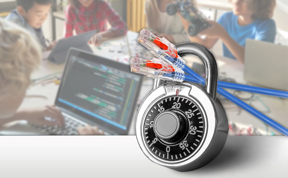
When it comes to physically protecting assets, IT managers also need a straightforward way to recognize which connections are tamper-proof. That’s why Siemon’s LockIT Secure Connectivity System is highly visible with LockIt patch cords featuring a bright red locking tab and LockIT outlet locks brightly colored in yellow.

With more devices connected to the network than ever before, there’s more of a chance of a device being accidentally or intentionally disconnected. While intentional disconnects of devices like surveillance cameras can significantly impact safety and security, others that don’t support mission-critical applications (think TV, digital display, or vending machine in a common area) can still cause plenty of inconvenience for both users and IT staff when disconnected. And let’s face it—any unused outlet can be tempting for cyber criminals looking to access a network, and they will always be a target for gum or spitballs in a school environment.

Click HERE to learn more about how Siemon’s LockIT can help you easily and cost-effectively protect your network connections.

Siemon’s Value Vertical Cable Manager – Day 2 Considerations

By Brian Duval,

When Siemon developed its new Value Vertical Cable Manager (VVCM) system, most of its features and capabilities were based on input from a wide range of company types and job roles among channel partners, end-user customers, consultants and system integrators. For the contractors and integrators tasked with installing racks and cable management on the jobsite, the focus was all about user-friendly features to enable faster, more efficient Day 1 deployments, and that input resulted in key VVCM innovations:

  • Small, light modular design and packaging that is easier to store, transport, and move around the jobsite versus heavy, single-piece traditional 7-foot vertical managers.
  • Intuitive, tool-less assembly process that takes less than 5 minutes start-to-finish (check out a time-lapse assembly video here.)
  • Dual-hinged doors with spring-loaded “finger-operated” latches vs. snap on covers.

While those Day 1 VVCM features were also valued by end-users and consultants, the overall user/consultant demographic placed a higher premium and interest on Day 2 benefits. That is a logical outcome, as once the contractor has wrapped up the initial install, it is typically the end-users that are left to manage the ongoing moves, adds and changes to that beautifully installed cabling infrastructure. Day 2 is all about accessibility, scalability, and flexibility.

In terms of accessibility, the biggest challenge with most lower-cost vertical managers is the covers. These tend to be snap-on style plates that, while they can be removed to provide more or less unhindered access to the cable management space, are difficult to reattach properly. In fact, it isn’t uncommon to see snap-on covers left aside and not re-attached at all, which not only exposes the cabling pathways to potential disruption, it detracts from the space’s aesthetics.

Based on customer feedback, the VVCM was designed with proper doors. These doors are dual hinged so that they can be opened in either direction, providing excellent access regardless of the cable routing configuration or surrounding space challenges without the consistent need to remove the doors completely. However, if users prefer to remove the doors, the spring-release clips at each corner and easy-to-identify attachment points make re-attachment a quick and simple process.

Scalability should also be considered – and when thinking about cable managers, scalability equals room to grow. Like most vertical cable managers, the VVCM is available in a range of widths – the wider the manager, the more management space it provides. Choosing the best manager size for the application requires some pre-Day 1 foresight based on per rack equipment and patching field density, horizontal cabling density, and future expansions. As a general rule of thumb, it is far safer to go bigger than initial estimates if at all possible.

Once the system is installed, that extra management space will also make basic day-to-day maintenance easier by virtue of providing more room to work. Ongoing MAC work can be further simplified with well though-out, high-capacity cable and cord routing support, and the VVCMs cable management “fingers” were expressly designed to provide that support. Each finger opening aligns with the rack’s mounting spaces and can accommodate up to 48 Category 6A cables, providing a direct and orderly path from the rack-mounted equipment or patching ports to the vertical cable management space.

As cabling channels are re-routed, new channels are added, and additional equipment such as PDUs need to be deployed Day 2, the flexibility to reconfigure the cable management space becomes a key consideration. While most value-level vertical managers provide limited, static space for cabling support accessories such as cable ties, the VVCM’s rear divider plates offer an almost countless number of potential configurations. The plates feature integrated attachment points for cable tie-downs, ¼ turn cable management accessories, and fiber spools, as well as standard PDU mounting points, allowing the managers to support power cable management in addition to network cabling. The divider plates are custom mountable, allowing users to put management support where it is needed, and are reversible to provide more pathway space to either the front or back of the rack as needed.

These Day 2 considerations should be top of mind in a user’s cable management selection regardless of which solutions are on the short list, but a complete analysis must include costs. In the past, the market primarily offered lower-cost bare-bones options or feature rich premium solutions, with a significant cost delta between basic and premium options and little or no middle-ground options. The VVCM was specifically developed to fill that market gap. Combined with Siemon’s 2-Post Value Rack and RouteIT Horizontal Cable Managers, the VVCM completes an integrated rack and cable management solution that is both cost-competitive with basic options, yet offering enhanced features typically limited to more expensive premium systems.

To learn more about the new Value Vertical Cable Manager, visit Siemon’s eCatalog

  Category: Enterprise LANs, General
  Comments: Comments Off on Siemon’s Value Vertical Cable Manager – Day 2 Considerations

Siemon Labs Verifies Transmission Compliance of TERA® SPE 400m Channels

By Valerie Maguire,

Siemon recently announced its TERA single-pair Ethernet (SPE) cabling system supports 10BASE‑T1L over distances of up to 400 meters. This fully-shielded solution offers superior noise immunity, virtually zero emissions and so much transmission headroom that the need for field testing is eliminated.

To demonstrate typical transmission performance for this system, Siemon Labs collected transmission data for 400m SPE channels consisting of 4 TERA connectors, 375 m of solid category 7A S/FTP 4-pair cable, and 25 m of stranded 1-pair TERA patch cords. Each pair in the 4-pair cable was tested, with the 1‑pair TERA patch cords cycled thru each quadrant of the 4-pair TERA connectors in positions C1, C2, C3 and C4 as shown in Figure 1.

tera spe 400m channel diagram

Figure 1 – TERA SPE 400m Channel

Component List

  • C1, C2, C3, and C4 = TERA 4-pair outlet (part no. T7F-01-1)
  • 5m of stranded 1-pair shielded TERA patch cord (part no. T1-XXM-B06L)
  • 90m of solid 4-pair category 7A S/FTP cable (part no. 9T7P4-E10-06-R1)
  • 250m of solid 4-pair category 7A S/FTP cable (part no. 9T7P4-E10-06-R1) with TERA 4 pair field terminatable plugs (part no. T7P4-B01-1) at each end
  • 35m of solid 4-pair category 7A S/FTP cable (part no. 9T7P4-E10-06-R1)
  • 20m of stranded 1-pair shielded TERA patch cord (part no. T1-XXM-B06L)

The test results demonstrate that all four 400m TERA SPE channels exceed the requirements for 10BASE‑T1L specified in IEEE Std 802.3cg™-2019 by impressive margins. For example, the measured headroom for the key system parameter of insertion loss is greater than 45%. SPE channel performance is also specified in the developing ISO/IEC 11801-1 Amendment 1 and ANSI/TIA-568.5 Standards. The 400m TERA SPE channels also exhibit substantial headroom to these draft requirements.

The test report also confirms that the TERA mated connection provides current carrying capacity up to 2 Amps per conductor when tested in accordance with IEC 60512-99-002. The report is available upon request from Siemon Technical Services.

Full details on how existing TERA permanent links can easily be retrofitted to support 10BASE‑T1L applications, as well as how to specify new generic TERA permanent links capable of supporting both future IT and OT device connections and dedicated SPE device connections, can be found here: “TERA® SPE Deployment Solutions for Retrofit, Future-Proof New, and Day 1 SPE Installations“.

Video Demonstration:
Supporting Single-Pair Ethernet over 400 m of Category-Style Four-Pair Copper Cabling

  Category: General
  Comments: Comments Off on Siemon Labs Verifies Transmission Compliance of TERA® SPE 400m Channels

The importance of protecting fiber optic cabling infrastructure

By Christopher Homewood,

The importance of protecting fiber optic cabling infrastructure

LightWays Fiber Routing System

The number of optical fiber links between switches, storage area network (SANs), and equipment continue to rise in data center environments due to increasing data and bandwidth needs. As connections between core, SAN, interconnection, and access switches push to 50, 100, 200 or higher gigabit per second (Gb/s) speeds and require low-latency transmission to effectively manage larger volumes of data, fiber is emerging as the dominant media type for data center infrastructure. As the flexibility, scalability, and higher bandwidth offered by fiber continues to lead to the replacement of copper cables across the data center, market volume for fiber is expected to increase at a rate of more than one and a half times that of copper in the years ahead.

Copper vs Optical Fiber

As a data center manager, the challenge of routing and segregating increasing amounts of fiber from network distribution to SANs and server areas is always prevalent. You need to ensure those routes maintain fiber protection and cost-effectively facilitate change so that you can confirm optimal performance, uptime, and scalability in your data center.

The Need for Effective Fiber Optic Protection

Fiber is sensitive to stress, and it is imperative to maintain proper bend radius of fiber cable along its entire route-both during and after installation. The bend radius of a cable is the amount of bending the cable can handle before sustaining damage or signal loss that can limit bandwidth performance. When a fiber cable is bent beyond its minimum bend radius, light signals carrying data can leak out at the bend location. Maintaining proper bend radius becomes an even greater concern for higher-speed data center applications that have more stringent fiber loss requirements. Consider that 10 Gb/s Multimode applications have a maximum channel insertion loss of 2.9 dB, while higher-speed, 40, 100, 200, and 400 Gb/s applications have a maximum loss of just 1.9 dB.

The minimum bend radius of fiber cable depends on its diameter, overall construction, and whether or not it’s under tension (i.e., during installation). Generally speaking, the standard minimum bend radius for fiber is 20 times the cable diameter under tension and 10 times the diameter after installation. Maintaining the minimum bend radius can be especially difficult when routing fibers through cable managers in higher-density, tight spaces within racks and cabinets. While newer bend-insensitive fiber that is less susceptible to performance loss from bending can ease the burden by offering a greater bend radius of 15 times the diameter under tension, you still need to pay close attention to bend radius throughout all pathways to achieve maximum performance. Best practice to avoid problems is to select fiber routing systems, cable managers, and connectivity solutions with integrated bend radius protection throughout.

The physical bends that occur in a fiber cable are referred to as macrobends, but they are not the only bends you need to worry about. Small microbends in the fiber caused by pressure on the cable can also cause signal loss. Over time, these microbends can cause the glass to crack and render the fiber completely dark with no ability to pass any light signals, leading to downtime and additional time and money required to locate and repair the break.

macrobend vs microbend

One of the primary causes for microbends is fiber cable resting on a pressure point such as a basket tray rung, hard edge, or other nonconforming surface or transition points. They can also be caused by weight from other cables, which can occur from overloading pathways beyond recommended capacity. Cable routing systems specifically designed for fiber with flat surfaces and no hard edges at transition points go a long way to preventing microbends while also providing a more secure environment.

To prevent the overloading of pathways, you also want to make sure your routing system has plenty of capacity and can be easily updated to support more as your data center grows.

An additional benefit of fiber routing systems over traditional solutions such as wire ducting or basket tray is the additional security and fire protection offered. It’s important than when selecting a solution, that you opt for a halogen-free option, this will provide additional peace of mind that if the worst were to happen that your infrastructure and employees will have maximum protection.

Changing Technology Demands Additional Flexibility and Scalability

With transmission speeds and the number of data center fiber links on the rise, it is also important that your data center’s fiber routing system makes it easy to access the entire route, allowing the addition of new fiber or replacing existing fiber to support new applications. At the same time, the increasing complexity of the overall data center environment may have you facing some additional challenges when it comes to routing fiber between critical areas and equipment.

As new technology and applications emerge and data centers become highly virtualized, switch-fabric mesh architectures (i.e., spine-leaf) that support low-latency networking also mean multiple redundant paths to connect every switch to every other switch. The dynamic nature of highly virtualized data center environments doesn’t just mean more fiber; it also means more fiber routed to more spaces and more equipment. If you’re dealing with a large data center environment segregated into multiple interconnected switch fabrics, you likely know just how complicated fiber routes can be.

Lightways

Maintaining and managing diverse fiber paths in these complex, highly dynamic environments demands routing systems that are flexible and scalable by design to enable reconfiguring existing routes or adding new routes easily and quickly. When it comes to reconfiguring or adding to a routing system, it’s also better to avoid tool-based connections that require drilling and screws as they require more time and incur further labor costs, as well as creating additional dust and debris which is best avoided in these critical environments.

Discover how Siemon’s LightWays can help you protect, segregate, and manage your data center’s ever-increasing and complex fiber infrastructure to ensure maximum performance, uptime, and scalability.

Other recent blogs we think you’ll like:

  Category: Data Center, Fiber, General
  Comments: Comments Off on The importance of protecting fiber optic cabling infrastructure

The Rise of IIoT Technology

By Brian Baum,

2021-rise-of-iiot-tech-header

The Rise of IIoT Technology

While the concept of the Internet of Things (IoT) has been around for a while, Industrial IoT (IIoT) has been getting a lot of attention lately due to its rapid growth and the promise of optimized operations, productivity and efficiency in industrial environments. And now with more ways to connect IIoT devices, the global IIoT market is expected to reach nearly USD $1 trillion by 2025.

IoT vs. IIoT

While IIoT is technically a subcategory of the broader IoT concept, it relates primarily to digital devices such as meters, sensors, actuators and controllers used in industrial environments, creating the foundation for automation via smart technology that is often referred to as Industry 4.0.

From a networking standpoint, IIoT devices are typically associated with Operational Technology (OT) networks that handle machine-oriented monitoring, control and supervisory data via Industrial Ethernet. In contrast, IoT has become synonymous with commercial and consumer devices associated with information technology (IT) networks that primarily handle business- and consumer-oriented data via commercial Ethernet. While IT and OT networks are converging in terms of sharing data to optimize industrial processes, there remains some fundamental differences between how IoT and IIoT devices communicate, how much bandwidth they need and the components they use.

While both IoT and IIoT devices utilize Ethernet frames to send data packets to and from networked devices, IIoT devices require time-sensitive networking (TSN). Unlike commercial Ethernet that cannot determine the time it takes for a given packet to arrive at its destination due to collision detection (i.e., waiting to transmit data when another device is also attempting to transmit), communication between industrial devices cannot have even the slightest delay and requires prioritization and time synchronization mechanisms via specific industrial Ethernet protocols.

Unlike many IoT devices that require high-speed data rates of 1 Gb/s or higher to transmit greater amounts of data like high-definition video, the majority of IIoT devices are low-speed and only require data rates less than 100 Mb/s. Many industrial Ethernet applications also use bus topologies where multiple devices share a common link, versus commercial Ethernet that is almost always configured in a star topology where each device has its own link. Industrial devices also often require longer link lengths to effectively traverse expansive manufacturing spaces to remote locations.

It’s also important to note that the components used to connect IIoT devices often need to be protected from harsh environmental factors such as mechanical forces (e.g., crushing and vibration), ingress of liquids and dust, chemical or climatic issues (e.g., temperature and corrosive solvents), and electromagnetic interference (EMI). That’s why many IIoT device connections require Ruggedized cables and connectivity.

New Ways to Connect

IIoT technology is being driven in part by emerging applications that will offer significant benefits over traditional fieldbus communication protocols historically used for industrial devices found in control and automation systems. Many traditional fieldbus systems operate over a wide range of media with varying lengths and connector interfaces, which are often proprietary and not interoperable. Not only has this made for more costly, complex deployments, but it has significantly limited the ability for industrial devices at the I/O level to effectively transmit and share information across OT and IT networks.

Traditional 4-pair Ethernet applications used in the commercial enterprise are cost-prohibitive for IIoT device connections. That’s why the IEEE developed the 802.3cg 10BASE-T1L standards for single-pair Ethernet (SPE) that supports 10 Mb/s Ethernet transmission over balanced single-pair cabling up to at least 1000 meters, as well as the delivery of DC power using IEEE 802.3 power over data lines (PoDL).

The emergence of SPE essentially provides a convergence communication application that solves the need to support IIoT connections up to 10 Mb/s with non-proprietary category-style cabling, while also providing a common networking platform for IT/OT convergence.

Another emerging application for connecting IIoT devices is newer next-generation Wi-Fi 6/6E, which offers real-world data transmission rates of greater than 5 Gb/s, longer device battery life, the ability to connect more devices and improved security that may make it feasible for connecting wireless IIoT devices. This could be extremely beneficial for connecting to wireless sensors and devices located in remote and hard-to-reach areas of the industrial environment, as well as mobile IIoT devices such as those used for inventory management and asset tracking and monitoring. In fact, a new report from Guidehouse Insights, entitled Wi-Fi 6 and the IIoT, examines how IIoT and Wi-Fi infrastructure can be used for industrial sites and estimates that industrial Wi-Fi infrastructure will grow from $1.7 billion in 2021 to $6.9 billion in 2030 at a compound annual growth rate of 16.8%. An executive summary of the report is available here for free download on the Guidehouse Insights website.

With its higher-frequency radio waves that offer speeds up to 10 Gb/s and reduced latency, there’s also much potential for 5G cellular to connect to IIoT devices, particularly those used in distributed telemetry applications and remote mining, excavation, smart grid/substation, and rail and transit applications. While Wi-Fi is ideal for wireless IIoT devices permanently located within a structure, distributed antenna systems (DAS) can extend 5G signals over the building campus to effectively support seamless wireless communications for mobile IIoT devices that need to operate both inside and outside of a facility. For example, consider the sensors being used to monitor and track shipments and temperature of new COVID-19 vaccines that must remain at minus 70°C to maintain effectiveness.

We’ve Got You Covered!

As buildings and factories becomes smarter and more efficient via IoT and IIoT technology, and IT and OT networks continue to converge, you need the right infrastructure in place to support it all. Whether you’re connecting devices to the IT network or the OT network, in commercial environments or industrial, Siemon has you covered with the right low-voltage system to support direct SPE and 4-pair wired Ethernet connections to devices, as well as connections to Wi-Fi access points and DAS nodes.

To learn more, check out these resources: