Category: General


From the New Norm to a New Future: Ensuring Business Continuity

By Christopher Homewood,

Entrepreneur working with laptop

There’s no doubt that 2020 had a huge impact on societies around the globe, changing how we live, work and conduct business. Data centers had to quickly respond as the COVID-19 pandemic forced businesses to shift to remote working and provide some semblance of “business as usual” via online collaboration, virtual events, enhanced e-commerce and digital customer services.

As a managed service provider, you’re not alone if your customers’ sudden need for increased bandwidth, VPN usage and cloud-based platforms had you scrambling to expand capacity, while still delivering assured availability. This reactive approach put massive pressure on existing data center infrastructure, but what may have seemed like a messy, temporary band aid at the onset of the pandemic is now a reality for the foreseeable future. It’s become increasingly evident that we’ve transitioned into a “new norm” with many businesses continuing to expedite their digital transformation plans and showing no signs of slowing down.

Successfully maintaining business continuity in 2021 and beyond places newfound emphasis on the need for your data center infrastructure to ensure low-latency performance, maximize reliability while enabling rapid deployment and scalability. This demands a forward-thinking approach to ensure you have an optimized DC design in place with the right architecture, topology and components to support you for the long term.

Navigating a Complex Landscape

When it comes to taking a step back from impromptu, improvised response in your data center and focusing on long-term digital transformation and business continuity, there are several considerations to keep in mind as you navigate the complex landscape of design and deployment options.

Hyperconverged infrastructure technologies and techniques adopted by the likes of Google, Microsoft and other large hyperscale data centers are no longer out of reach for your data center thanks to advanced open-source protocols, white-box hardware and software-defined networking. These high-density, highly virtualized server environments are ideal for enabling the cost-effective expansion and scalability you need to support your customers’ digital transformation.

But with virtual environments distributing resources across multiple servers located anywhere in the data center, dynamic server-to-server communication demands low latency, high-bandwidth transmission. This requires taking a closer look at your architecture and topologies and choosing a design that reduces the number of switches that data must traverse, enabling more east-west traffic between servers rather than north-south traffic through multiple tiers of switches. It also means determining where to locate equipment and how to connect it to best meet your current and future manageability, flexibility, scalability and security needs.

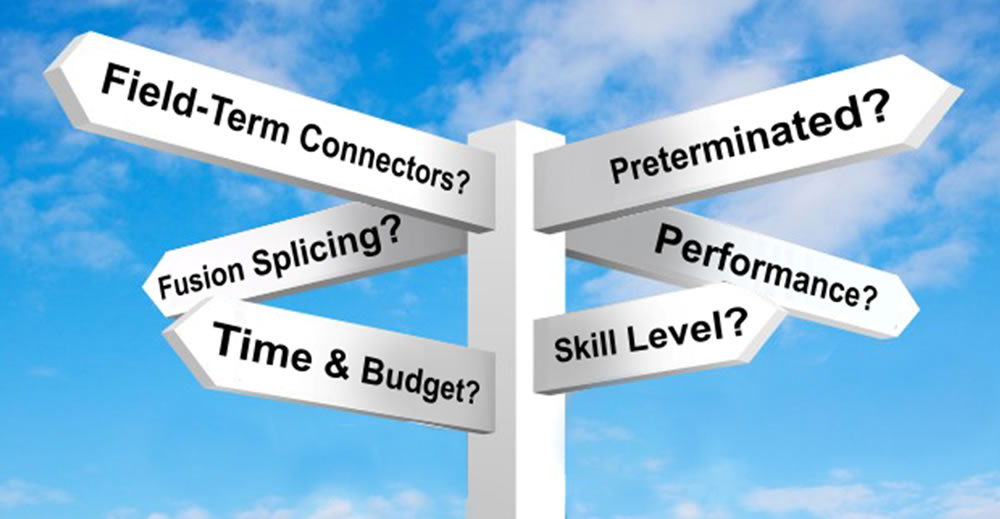
At the same time, innovations in switching technology have established an easier migration path to 25, 50 and 100 Gb/s speeds in switch-to-server connections with 100, 200 and 400 Gb/s speeds in backbone links. There are now more options than ever for supporting these speeds-from twinax Direct Attach Cable (DAC) assemblies and Active Optical Cables (AOCs) for direct equipment-to-equipment links, to multiple Multimode and Singlemode fiber applications using parallel optics with multi-fiber connectivity (i.e., MPO/MTP) or wave division multiplexing (WDM) technologies. With a range of distance capabilities, power consumption, performance, and material and installation costs, it can be difficult to navigate the options and know which solution provides the right combination of cost, performance, reliability and scalability to best meet your MSP model and budget.

Therefore, Trusted Guidance is Essential

As technology continues to evolve and digital transformation ramps up with the new norm that has become the new future, managed services will continue to be critical for supporting business needs across all market sectors. As a managed service provider, you need to be ready to support your customers and set yourself up for a successful 2021 and beyond.

When it comes to designing and deploying data center infrastructure for business continuity, you need a partner with the expertise, end-to-end solutions and associated services to ensure you can effectively and quickly expand your available services no matter what comes your way without jeopardizing your operational performance.

With value-added Data Center Design Services and a full range of high performance fiber, high speed interconnects and copper systems to support 10 to 400 Gigabit applications and beyond, Siemon can ensure:

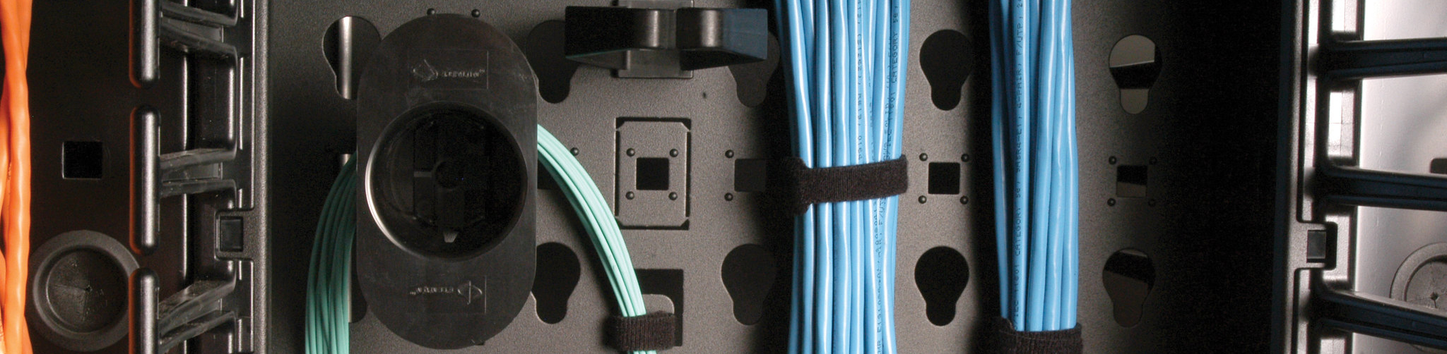
  • Worry-free infrastructure – via non-blocking, low-latency architecture and topologies that support emerging technologies and effective hyperconverged environments.
  • High-density, flexible solutions – that ease expansion while ensuring manageability, security and compliance.
  • Reduced complexity, risk and costs – with consistent beyond-standards performance and quality across all systems, regardless of the application.

Backed by industry leadership, renowned technical service, a strong data center partner ecosystem and excellent supply chain logistics, Siemon doesn’t just help you design and deploy data center infrastructure for today, our experienced teams work with you to design, implement and deliver a high quality infrastructure approach backed by a comprehensive service offerings that prepare you for the challenges ahead.

Learn more about how Siemon can help you maintain business continuity in 2021 and beyond.

Other recent blogs we think you’ll like:

  Category: Data Center, General
  Comments: Comments Off on From the New Norm to a New Future: Ensuring Business Continuity

IoT/IIoT Connections in Unforgiving Environments

By Brian Baum,

2020-12-iot-header

Ruggedized image

Over the past decade, we’ve heard a lot about the Internet of Things (IoT) and how it will transform our daily lives. While IoT has become a bit of an overused and often misused term, no one can deny the growing number of connected “things” collecting and transmitting data via Internet protocol (IP) over Ethernet-based networks. This is also happening in the industrial environment with the proliferation of industrial Ethernet and more connected industrial devices and machines to support supervisory, control, monitoring and collection of real-time production data. As a result, we now also hear quite a bit about Industrial IoT (IIoT) and how it will transform the manufacturing industry.

While IoT and IIoT both relate to the concept of devices communicating via IP, and they share some common connector interfaces and intelligence, they are in fact quite different in terms of their primary use and goal. IoT refers primarily to commercial applications used by consumers and end users with a focus on everyday systems that support business needs, communication, safety, security, health and wellbeing with the primary goal of improving business outcome and daily life. In contrast, IIoT refers primarily to industrial applications used by machines and production equipment with a focus on automated control and monitoring to improve efficiency, maximize productivity and optimize operations.

There are other key differences between IoT and IIoT networks including Ethernet application requirements (i.e., collision detection vs. deterministic real-time Ethernet) and topology variations, but often one of the most talked about differences are the environmental factors to which these networks are exposed. These include potential mechanical forces (e.g., crushing and vibration), ingress of liquids and dust, chemical or climatic issues (e.g., temperature and corrosive solvents), and electromagnetic interference (EMI). While industrial environments and IIoT devices are most often associated with these factors, the proliferation of IoT means that devices communicating via standard commercial Ethernet may also be located in more unforgiving environments than ever before. Whether it’s point-of-sale machines in outdoor eateries, Wi-Fi access points in a science laboratory, security cameras at a marina or medical equipment in an operating room, cables and connectors use to establish connections can also be at risk. That means many of the cable and connectivity characteristics required for IIoT may also be required for IoT.

Thankfully there are industry standards that look at these environmental factors using the MICE (Mechanical, Ingress, Climatic and Electromagnetic) method of classification and consider each of them at various levels of harshness, including Level 1 for everyday commercial office environments, Level 2 for light industrial and Level 3 for industrial. MICE parameters can be instrumental in selecting cables and connectors for both IoT and IIoT connections. Let’s take a look at a few characteristics to meet various MICE parameters.

increasing severity

Sealed for Ingress Protection

Connectors are of important consideration in unforgiving environments because they can be a source of ingress. When dust and liquids infiltrate network connections, contacts within jacks and plugs can become corroded and no longer maintain connectivity. For example, consider an operating room in a hospital where mobile heart monitors, respirators and other machinery are wheeled in. Solvents used to disinfect the environment can infiltrate unprotected equipment connections and over time potentially cause those connections to malfunction, which could be catastrophic in that environment.

Ingress doesn’t just apply to liquids. The “I” in standards-based MICE parameters also looks at particulate matter (i.e., dust and debris) and classifies the level of protection based on the maximum diameter of a particulate. For example, a Level 1 commercial environment allows for a maximum particulate diameter of 12.5 millimeters while Level 2 and Level 3 environments allow a maximum of 50 micrometers. One standards-based rating to consider for unforgiving environments is ingress protection (IP) ratings developed by the European Committee for Electro Technical Standardization (CENELEC). Sometimes referred to as an IP code, the IP rating consists of the letters “IP” followed by two digits-the first digit classifying protection against solids (e.g., dust) and the second classifying protection against liquids (e.g., water). A common IP rating for ruggedized network connectivity is IP67, which offers total protection against dust ingress and water ingress.

It’s not always just the outlet and plug interface to consider when it comes to ingress protection. IP44-rated stainless steel faceplates with rear sealing gaskets provide a protective seal that prevents moisture and debris from infiltrating the space behind the wall where outlets are terminated to the cable. Note that connections that reside within enclosures may not require additional projection and an IP67 rating, but the enclosure itself may need to offer protection. The National Electrical Manufacturers Association (NEMA) uses a standard rating system for enclosures that includes IP code equivalents. For example, a NEMA 4X enclosure offers the equivalent of an IP66 rating.

Protection Against Solids
0No special protection
1>50 mmProtected against objects greater than 50 mm (e.g., accidental touch by surface of human hands)
2>12.5 mmProtected against solid objects greater than 12 mm (i.e., human finger size)
3>2.5 mmProtected against solid objects greater than 2.5 mm (e.g., tools, thick wires)
4>1 mmProtected against solid objects greater than 1 mm (e.g., most wires, screws, paperclips)
5Dust ProtectedProtected against limited dust ingress (e.g., protection against contact but no harmful deposit of dust)
6Dust TightTotally protected against dust
Protection Against Liquids
0No special protection
1Dripping waterVertically falling drops have no harmful effect
2Dripping water with 15-degree tiltVertically falling drops have no harmful effect if enclosure tilted up 15 degrees
3Spraying waterWater falling as spray at any angle up to 60 degrees from the vertical has no harmful effect
4Splashing waterWater splashing from any direction has no harmful effect
5Water jettingWater projected (12.5 mm nozzle) from any direction has no harmful effect
6Immersion up to 1 mImmersion in water under defined conditions of pressure and time (up to 1 m) has no harmful effect
7Immersion above 1 mContinuous immersion as specified by manufacturer has no harmful effect. Typically hermetically sealed.

The Vibration Factor

IoT/IIoT connections that are subjected to consistent vibration and movement such as those on machinery or in proximity to drive belts, motors, pumps, fans and other equipment, can experience problems due to misalignment, disconnects and long-term wear caused by loosening. One way to help prevent the impact of vibration is to use bayonet-style mating connectors like Siemon’s Ruggedized copper and fiber connectors. Ruggedized cables that feature an over-molded 90-degree angle can also help maintain vibration for connections versus manual bending of straight connectors that can increase the potential for connectors to come loose.

vibration factor

For even more protection against vibration, some devices will also often make use of M series connectors such as D-coded M12 connectors us in 100 Mbps Ethernet applications. These connectors feature a highly durable impact-resistant circular design that utilizes a locking thread to prevents them from loosening and becoming disconnected or misaligned. They are also IP67 rated for protection against ingress and shielded for protection against EMI. The overall smaller size of the M12 is also ideal for supporting the trend toward smaller IIoT devices and sensors in more places. Siemon offers M12 cable assemblies for these applications.

Cable Construction and Jacket Materials Matter

When it comes to protecting cables in unforgiving environments, the overall construction of the cable and its jacketing materials may need to be considered. For example, environments subjected to EMI from other equipment (e.g., fluorescent lights, air conditioners, X-ray machines, motors, actuators, etc.) should use shielded cabling. EMI can produce disturbing signals that can degrade transmission performance, and the cable shield protects data from those signals. This can be especially critical in an environment like a hospital where proper transmission of data could impact the reliability of life-saving applications. Note that optical fiber cable used to support above 10 gigabit per second transmission speeds, extended distance requirements and backbone cabling is inherently immune to EMI.

Other characteristics to look for in cables might be increased operating temperature durable jacketing and the use of more jacket materials that are resistant to the various environmental elements present in production and other harsh environments. While polyvinyl chloride (PVC) jacketing used for commercial-grade cables can support some light industrial environments, other environments might need a little something more. For example, thermoplastic elastomer (TPE) jacket materials support wider operating temperature ranges and are more resistant to sunlight, moisture, abrasion and corrosive chemicals, while polyurethane (PUR) is bit more mechanically tough with a higher tensile strength and tear resistance for use on machinery. That’s why Siemon Ruggedized Category 6A shielded cable assemblies are available with a TPE jacket and our M12 cable assembles feature a PUR jacket.

Learn more about our Ruggedized line of cabling and connectivity. And listen to our recent Network Connections Podcast Episode 7 on How to Protect Critical Connections in Unforgiving Environments.

  Category: General, IoT
  Comments: Comments Off on IoT/IIoT Connections in Unforgiving Environments

Cost-Conscious Rack and Cable Management Options Vs. The “New Everyday” Install

By Brian Duval,

Vertical Cable Manager

When it comes to racks and cable management, it seems like there’s always been a de facto line between basic, more or less bare-bones options aimed at typical, day-to-day contractor needs and feature rich premium solutions for higher-end “project work”. And, as any cabling pro can attest, crossing the line into premium solutions usually means a hefty price increase. That may not have been so much of an issue in the good old days, when those everyday jobs rarely required anything more than bare-bones racks and cable managers; but as technology advances, those routine small and medium installs start to feel far less routine.

With technologies like IP-based A/V, surveillance, access control, WiFi, and other intelligent building systems not only communicating through the IT cabling infrastructure, but being powered by it through PoE, the density and complexity of the network can quickly outgrow the capabilities of contractor-priced, basic rack and cable management options. Toss in larger-diameter category 6A cables, and installers are often forced to either live with the limitations of the basic solutions and figure out a way to shoehorn 10lbs of, umm . . . “network infrastructure” into a 5lb bag, or upgrade to more expensive premium options. To make a long story short (or at least shorter), the market was missing a complete rack and cable management solution that could meet “value-level” price points for day-to-day work, and offer the enhanced features needed to support the increasing demands of those everyday jobs . . .

(Now, if I was going for the full-on marketing hard-sell here, I could follow that last sentence up with something like “. . . UNTIL NOW” – but since you’re probably as sick of hearing that kind of thing as I am, I’ll just get to the point.).


Value Vertical Cable Manager systemSiemon just launched a new Value Vertical Cable Manager (VVCM) system. I’ll cover its features in a second, but I want to start with what this launch means from a system standpoint. Combined with Siemon’s 2-Post Value Rack and RouteIT Horizontal Cable Managers, the VVCM completes a comprehensive, unified rack and cable management family that is both cost-competitive vs. the common, stripped-down options, and packed with features typically found only on premium systems. To put it another way, this value-priced system is designed to simplify the deployment and long-term management of the “new everyday” install: efficiently handling high-density patching and backbone cable routing with capacity for future scalability, providing equipment mounting flexibility for a wide range of applications, supporting space-saving power distribution and cord management options – everything you expect from the premium-level systems, but without the premium price tag.

Back to the new Value Vertical Cable Manager. Rather than make you read about all of its cool contractor-focused features and innovations, we’ve created a brief video for you. (Frankly, the video only takes a couple of minutes, and covers more detail than I could manage in 4 or 5 more pages worth of writing). Check it out on the Siemon eCatalog.

Just in case you can’t spare a second to watch the video now, I’ll give you a Value Vertical Cable Manager teaser:

  • It ships small and light, so it is easier handle in the warehouse, on the truck, and at the jobsite. (No more lugging heavy boxes around or cramming huge 7-ft boxes in elevators.
  • It only takes 5 minutes to install. Other than bolting it to the rack, assembly is tool-less
  • It has REAL DOORS. No more dealing with those snap-on covers. You know: the ones you can never seem to get back in place without a 5-minute wrestling match and a few mangled fingers (both your fingers and the cable manager fingers). The VVCM has real, spring-loaded latches that you can operate with one finger.
  • There’s tons more to talk about on the eCatalog

  Category: Enterprise LANs, General
  Comments: Comments Off on Cost-Conscious Rack and Cable Management Options Vs. The “New Everyday” Install

Which Fiber Termination Method is Right for You?

By Brian Baum,

2020-06-fiber-term-feat

Which one right for you

When it comes to deploying fiber links in the data center and telecommunications rooms, there are several different options ranging from pre-terminated and fusion splice options, to field-terminated connectors. When it comes to choosing one of these methods, there are several factors to consider that can help you determine the best option for your specific scenario.

First and foremost, you need to consider the immediate applications and equipment interface requirements, as well as future scalability plans. For example, if you plan to deploy a high-speed parallel optics application like 100GBASE-SR4 or 200GBASE-SR4 that require multi-fiber MTP connectors, this may limit your termination method since MTPs are not available in all termination methods. While budget will always be a decision factor, you will also want to consider the number of connections, the project schedule, insertion loss performance, the level of expertise of those doing the installation and the overall environment where the installation will occur. With these factors in mind, let’s take a closer look at your options.

Pre-terminated Fiber Solutions

fiber solutions

Available in multiple fiber types, counts and connector interfaces including Multimode and Singlemode fiber types and multi-fiber MTP, LC, SC, ST connector interfaces, Siemon’s Base 12 and Base 8 pre-terminated solutions feature pre-terminated cable assemblies that simply plug into modules or cassettes house within an enclosure. With low-loss options, MTP connectivity and hybrid MTP-to-duplex assemblies, these solutions readily support high-speed parallel optic and breakout applications.

Because they are 100% factory-terminated and tested with a plug-and-play deployment, pre-terminated solutions require no fiber termination skills and result in less variability and superior performance. They are also considered a greener option due to less packaging, consumables and onsite waste. Pre-terminated solutions are preferred for high-density, large installations as they save pathway space and allow for quickly terminating large fiber counts. While these solutions do cost more in material and are made to order, if lengths can be carefully planned, the labor savings and faster deployment time can outweigh any material premium. In fact, these solutions can be deployed up to 90% faster. However, they may not be the most cost effective in low fiber count duplex applications, and they are not well suited for disaster recovery or other quick turn-around deployments due to planning and longer lead times.

Splice-On Pigtails

Siemon’s splice-on pigtails are available in Multimode and Singlemode and various connector types, including duplex and simplex LC, SC and multifiber MTP. Splice-on pigtails feature a short fiber stub that protrudes from a pre-polished connector and is fusion spliced to the incoming fiber using an electric arc. This process requires a fusion splicing machine that aligns two cleaved fibers and fuses them together. There are also mass fusion splicers that fuse 12-fibers in a ribbon cable at once.

splice-on pigtails

Splice-on pigtails offer a strong, low-loss connection, typically around 0.1dB, with the least amount of reflectance. These solutions are ideal for transitioning from 250µm OSP to 900µm indoor cable, which is why you see them used a lot in entrance facilities for incoming fiber – especially in cloud and colocation data centers where there is fiber coming in from various service providers. They also don’t have a lot of onsite waste, cost less than pre-terminated solutions from a material standpoint, and they offer the benefit of not needing to plan exact lengths or deal with longer lead times.
However, splicing can be expensive for anyone who doesn’t own a splice machine – although renting a splicing machine is an option. There is also the added cost and space required for the splice trays and sleeves to house and protect the splices. The performance of these solutions is also highly dependent on the quality of the cleave so a high-quality cleaver is recommended. From labor standpoint, the fusion process does require more time compared to pre-terminated solutions, and you need to have a decent workspace to accommodate the process.

Splice-On Connectors

Siemon Optifuse

Pre-polished fusion splice-on connectors like Siemon’s OptiFuse™ are available in Multimode and Singlemode and with LC or SC simplex connectors. Instead of splicing to a pigtail stub, with splice-on connectors, the stub resides inside the connector. The stub is fusion spliced, and the connector parts are assembled around the ferrule.

Like splice-on pigtails, splice-on connectors offer a strong, low-loss connection without the need to predetermine lengths and require a fusion splicing machine and a quality cleave. Splice-on connectors can terminate 250µm coated fiber, 900µm tight buffered fiber and 900µm breakout kits. However, with splice-on connectors there is no need for splice trays and protective splice sleeves since the splice is protected within the connector housing itself. This reduces material requirements, conserves space within fiber enclosures and can save up to 30% on installation time compared to pigtails.

Field-Terminated Connectors

For field-terminated connectors that do not require splicing, there are generally two options-epoxy/polish connectors like Siemon’s LightSpeed™ connectors which are available in SC, LC and ST in both Multimode and Singlemode and mechanical splice connectors like Siemon’s LightBow™ connectors, which are available in SC and LC in both Multimode and Singlemode. While not ideal for ultra-high density installations or very tight insertion loss budgets that require less than 0.2dB insertion loss per connector, field-terminated connectors are perfect for lower fiber counts, repairs and reconfigurations-especially for situations where installers do not have the luxury of planning and lead times associated with pre-terminated solutions or do not own an expensive fusion splicer as required for splice-on pigtails or splice-on connectors.

Epoxy/polish connectors use epoxy to join the fiber and the connector ferrule, and the epoxy is then cured. The protruding fiber must be cleaved and polished to ensure smooth flush finish before connecting. While many experienced fiber technicians may prefer epoxy/polish connectors, they are not the best option if there is a limited skill set-their average insertion loss is about 0.2 – 0.3dB for those who are experienced but could be much higher for those who are not. Because the end face is exposed and polished in the field, care also needs to be taken to prevent contamination. Epoxy/polish connectors require the most consumables and results in the most waste of all the fiber termination options.

Siemon LightBow

Mechanical splice connectors where two fibers are joined in an alignment fixture using index matching gel have become a more popular field-terminated connector option as they offer faster termination with no cure time, are not difficult to terminate and offer limited waste with less consumables compared to epoxy/polish connectors. When selecting a mechanical splice connector system, consider that Siemon’s LightBow system features a low-cost termination tool with no power or batteries required that can terminate a connector in less than one minute, which is not the case with all manufacturers’ mechanical connector systems. There is also a lower risk of contamination for solutions like LightBow where the dust cap can be left on during the termination process.

We Can Help You Choose

To better help you select a fiber termination method, we’ve put together the following summary chart. Our superior technical support is also always available to discuss your options and determine the best solution for your specific situation and budget. The good news is that no matter which solution ends up being right for you, Siemon offers ALL the options as part of our Advanced Fiber Solutions.

2020-06-fiber-term-5

  Category: General
  Comments: Comments Off on Which Fiber Termination Method is Right for You?

5 Tips for an Effective BOM

By Brian Baum,

Tips for an Effective BOM

Low-voltage cabling infrastructures are becoming more complex than ever. LANs have more connected devices in more locations and data centers are shifting to fully-meshed leaf-spine architectures where every switch is connected to every other switch via redundant pathways. With these complexities come a wider variety of copper and fiber cable and connectivity components and associated racks, cabinets and cable management needed to build reliable, high-performance networks-and that means more extensive and diverse project bills of material (BOMs).

When it comes to generating a BOM for a project bid proposal, inaccuracy and lack of detail is a surefire way to lose the bid opportunity or lead to unexpected costs and scheduling delays during the implementation stages if the bid is won. And if you’re putting together pricing for discretionary work with an existing customer, failure to include all the right parts and pieces will most definitely cost you time and money. We’ve put together the top 5 tips to make sure your BOMs have all the ingredients necessary for success.

1. Include the Right Amount of Detail

A general rule of thumb when it comes to creating a BOM is the more detail, the better. Don’t assume that your customer is going to recognize part numbers and acronyms. At the very least, your BOM should include part numbers, product name and description, manufacturer and quantities. Including additional information like intended application and location, dimensions, color, units of measurement and product resource links for customer use drawings, spec sheets and installation instructions can also be helpful.

2. Check and Double Check for Omissions

There are many ways that a network infrastructure project can go over budget but leaving components off your BOM should not be one of them. If you’re working off a fixed bid, the cost of omitting components can be passed on to you-and it can cause project delays that cost you even more and ultimately damage your reputation. And it’s not just components you need to worry about. Don’t forget all the labor costs, including time for testing and labeling of the network that can add up to thousands of dollars. Even not-so-obvious soft costs like temporary power, disposal fees and site prep should be included. Using a checklist as you prepare your BOM is a good idea, and make sure to go back and double check (or maybe even triple check). It also never hurts to have a second pair of eyes look over your BOM to make sure you didn’t miss anything.

3. Do Your Homework

Before finalizing your BOM, it’s best to work with your manufacturer and distributor to verify costs, availability and lead times. Verifying this information early during the planning phase can help avoid the extra time and cost involved in finding replacement products or introducing schedule delays. This is especially important for the components that have the highest monetary value and those required for the first stages of installation. While you might be able to wait for those special-order purple patch cords until later in a project, not verifying availability on the bulk cable needed for the job can delay the project start date (and your revenue). If there’s any flexibility in the project specs, you may even want to identify any alternative components ahead of time as a back-up plan.

4. Don’t Make Assumptions

Before you build your BOM, make sure the plans and spec are clear so that you know exactly what’s expected from both a material and labor standpoint. Check with the customer on any areas of a project spec that seem vague. If something looks “off” to you, it very well could be the spec that’s the problem. The last thing you want to do is leave off a critical line item because you “assumed” it wasn’t included in the spec even though your intuition and experience told you that it should be.

5. Use Siemon’s Automatic BOM Generation Tool

One of the biggest barriers to building an accurate BOM is using outdated manual processes. Thumbing through a paper catalog and typing part numbers into a spreadsheet is not only time-consuming-it’s also a sure way to end up with errors, especially considering that a single component can have literally thousands of part numbers due to a wide range of attributes like performance level, construction, jacket type, color, size, length, polarity and packaging.

Automatic BOM Generation Tool

Using an online BOM generation tool like the one offered with Siemon’s new e-catalog lets you avoid manual errors and execute BOMs faster and more accurately, which can ultimately expedite pricing and give you a leg up on the competition. Our intuitive online BOM generator lets you filter product attributes to get to the right part number, specify quantities and automatically add them to a specific project BOM that can be exported into a spreadsheet, complete with detailed product description, product class and units of measure. And because the BOM generator is linked with Siemon’s existing internal system, you can rest assured that your BOM will include the most up-to-date product information.

To quickly and easily build an accurate BOM for your next low-voltage infrastructure project, click HERE to access our new best-in-class eCatalog with BOM generator.

  Category: General
  Comments: Comments Off on 5 Tips for an Effective BOM