Category: General


Beware the Arc in Powered Remote Network Devices

By David Wall,

In less than a decade, remote powering technology has revolutionized the look and feel of the IT world. Many IT managers aren’t aware that remote power delivery produces temperature rise in cable bundles and electrical arcing damage to connector contacts. Heat rise within bundles has the potential to cause higher bit errors because insertion loss is directly proportionate to temperature. In extreme environments, temperature rise and contact arcing can cause irreversible damage to cable and connectors. Fortunately, the proper selection of network cabling can completely eliminate these risks.

Video Demonstration:

Siemon shielded category 6A and category 7A cabling systems provides the following advantages that ensure a “future-proof” cabling infrastructure capable of supporting remote powering technology for a wide range of topologies and operating environments:

  • Siemon’s Z-MAX® and TERA® connecting hardware has been independently certified to comply with IEC 60512-99-001, which ensures that critical contact seating surfaces are not damaged from the arc that occurs when plugs and jacks are unmated under remote powering current loads
  • This arc poses no risk to humans, arcing creates an electrical breakdown of gases in the surrounding environment that results in corrosion and pitting damage on the plated contact surface at the arcing location. Note that in the Siemon contact design any potential damage due to arcing will occur well away from the final contact mating position.

Learn more in Siemon’s Tech Brief: “Siemon Advantages using Shielded Cabling Systems to Power Remote Network Devices”

Download PDF


  Category: General
  Comments: Comments Off on Beware the Arc in Powered Remote Network Devices

Tech Tip: Overcome data center floor space constraints – Easily add 4u of above-cabinet rack space

By David Wall,

When floor space in the data center is limited, look upward.  Look towards the space between the top of the cabinet and the bottom of ladder racks and cable trays.  Look towards Siemon’s Cable Tray Rack.

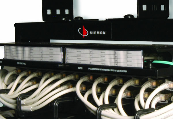
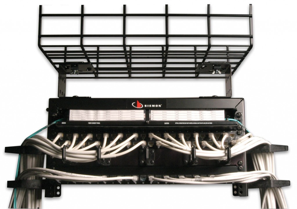
Designed to mount directly to overhead ladder rack or cable tray, Siemon’s Cable Tray Rack delivers 4U of easily installed and accessible 19” rack mount space above cabinets and racks without consuming additional floor space, making it ideal for use as a Zone Distribution Area (ZDA) or Equipment Distribution Area (EDA) in data centers.

Used with copper patch panels or fiber enclosures, the cable tray rack can increase cabling density, improve cable routing, simplify moves, adds and changes and provide pre-cabled connectivity for rapid deployment of new cabinets, racks and equipment.

Data Center Cable Tray Cable Patching

More Cable Tray Rack Benefits:

  • Improved Thermal Efficiency ­- Helps improve airflow by managing patching fields and cabling above cabinets and racks, minimizing obstruction of equipment cooling features.
  • Rapid Data Center Deployment -­ Can be used in conjunction with Siemon’s pre-terminated copper and fiber solutions to reduce installation time
  • Open Compatibility -­ The cable tray rack mount solution attaches to all common overhead cable tray and ladder rack systems, including Siemon’s RouteIT system.

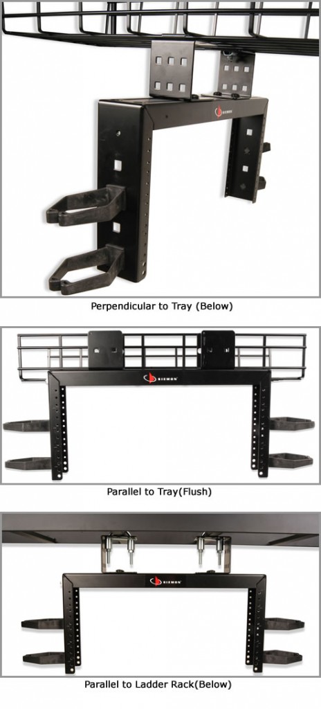
Mounting Option Examples

The unique design can be mounted below, flush or above cable tray in both parallel and perpendicular configurations.

Data Center cabinet patching above cabinet

Learn more about Siemon’s Cable Tray Rack and other Data Center Infrastructure innovations.


  Category: General
  Comments: Comments Off on Tech Tip: Overcome data center floor space constraints – Easily add 4u of above-cabinet rack space

How to Cross Reference ISO/IEC and TIA Naming Conventions

By David Wall,

With four new ISO/IEC and TIA cabling projects under development, it is more confusing than ever to cross reference the two group’s cabling and component specifications.  This short primer should help.

In ISO/IEC Standards, structured cabling components (e.g. cables, connecting hardware, and patch cords) are characterized by a performance “category” and are mated to form a permanent link or channel that is described by a performance “class”.  In TIA Standards, components and cabling are both characterized by a performance “category”.  ISO/IEC and TIA equivalent grades of cabling, arranged in order of increasingly more stringent transmission performance, are shown below.

ISO
(cabling)
ISO
(components)
corresponds toTIA
(cabling and components)
Class DCategory 5eCategory 5e
Class ECategory 6Category 6
Class EACategory 6ACategory 6A
Class ICategory 8.1Category 8
Class FACategory 7ANo equivalent
Class IICategory 8.2Class II*
* TIA  has substantial component-related work that needs to be done related to the specification of class II channels and the naming convention for components is unknown at this time.

Note that ISO/IEC class I/category 8.1 and TIA category 8 will not be electrical supersets of ISO/IEC class FA/category 7A.


  Category: General
  Comments: Comments Off on How to Cross Reference ISO/IEC and TIA Naming Conventions

Market Watch: Faster processors, convergence fuel growth of 40 Gigabit Ethernet

By David Wall,

Are you ready for 40 Gigabit Ethernet?

In a recent TechTarget article, David Jacobs argues that even smaller data centers and network backbones will undoubtedly require 40GbE.

The factors contributing to this trend include:

  • Faster processors and increasing server computing capability
  • Increasing virtualization usage and traffic from each server
  • Applications, such as big data, with multiple components on multiple racks
  • Mobile devices connected via 802.11n, 802.11ac or 4G putting pressure on backbones and data centers
  • Convergence of network and storage data

As 10GbE takes hold, the network must be upgraded. Jacobs points out the result:  “Upstream links to the core and to other aggregation devices must then be upgraded to 40 GbE or, in some networks, to 100 GbE.”

When preparing for the next generation data center, look towards Siemon Data Center Solutions to help you build the data center infrastructure ready for today and built for the future.


  Category: General
  Comments: Comments Off on Market Watch: Faster processors, convergence fuel growth of 40 Gigabit Ethernet

INFOGRAPHIC: Advantages of Structured Cabling versus Top of Rack (TOR)

By David Wall,

Infographic TOR versus Structured Cabling

Data Center and IT professionals: This infographic from Siemon examines the impact of top of rack (ToR) and structured cabling configurations on total management; scalability and upgrades; interoperability; equipment, maintenance and cabling costs; port utilization; power consumption and cooling requirements.  Structured cabling offers clear advantages.

The infographic is based on an actual 39 cabinet data center and the findings of a recent white paper by the Communications Cable and Connectivity Association (CCCA) (“Navigating the Pros and Cons of Structured Cabling vs. Top of Rack in the Data Center” – download PDF).

Infographic TOR versus Structured Cabling

Data Center Planning Resources:

  • Read white paper “Navigating the Pros and Cons of Structured Cabling vs. Top of Rack in the Data Center” (download PDF) by the Communications Cable and Connectivity Association (CCCA)
  • Learn about Siemon Data Centers Solutions.  Siemon has focused its cabling expertise into a global data center service team, capable of guiding you through the process of selecting, designing and deploying the business-critical cabling infrastructure upon which your entire data center will rely.

  Category: General
  Comments: Comments Off on INFOGRAPHIC: Advantages of Structured Cabling versus Top of Rack (TOR)